ARTIX-7 FPGA Development Board AX7101 User Manual
Part 3.6: Expansion Header
The AX7101 FPGA carrier board is reserved with one 0.1inch spacing
standard 40-pin expansion header J11 which is used to connect the ALINX
modules or the external circuit designed by the user. The expansion port has
40 signals, of which 1-channel 5V power supply, 2-channel 3.3 V power supply,
3-channle ground and 34 IOs. Do not directly connect the IO directly to the
5V device to avoid burning the FPGA. If you want to connect 5V
equipment, you need to connect level conversion chip.
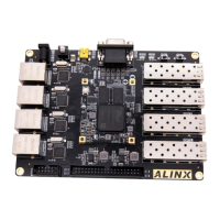
A 33 ohm resistor is connected in series between the expansion port and
the FPGA connection to protect the FPGA from external voltage or current. The
circuit of the expansion port (J11) is shown in Figure 3-6-1.
Figure 3-6-1: Expansion header J11 schematic
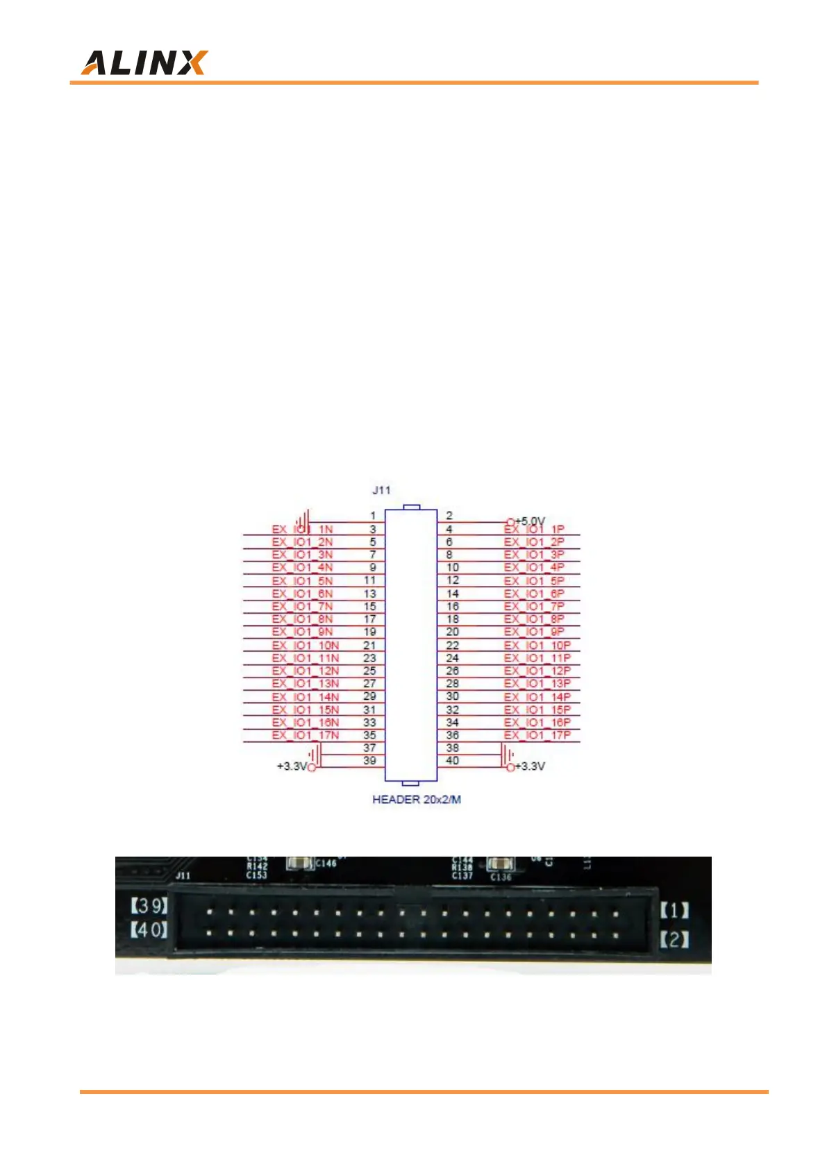
Figure 3-6-2: Expansion header J11 on the Carrier Board