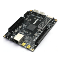
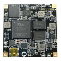
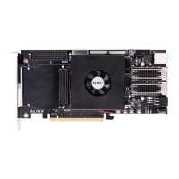
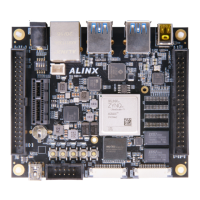
ARTIX-7 FPGA Development Board AX7101 User Manual
VSYNC pins. Pins 1, 2, and 3 are red, green, and blue primary color analog
voltages, which are 0 to 0.714V peak-peak, 0V is colorless, and 0.714V is full
color. Some non-standard displays use a full color level of 1Vpp. The three
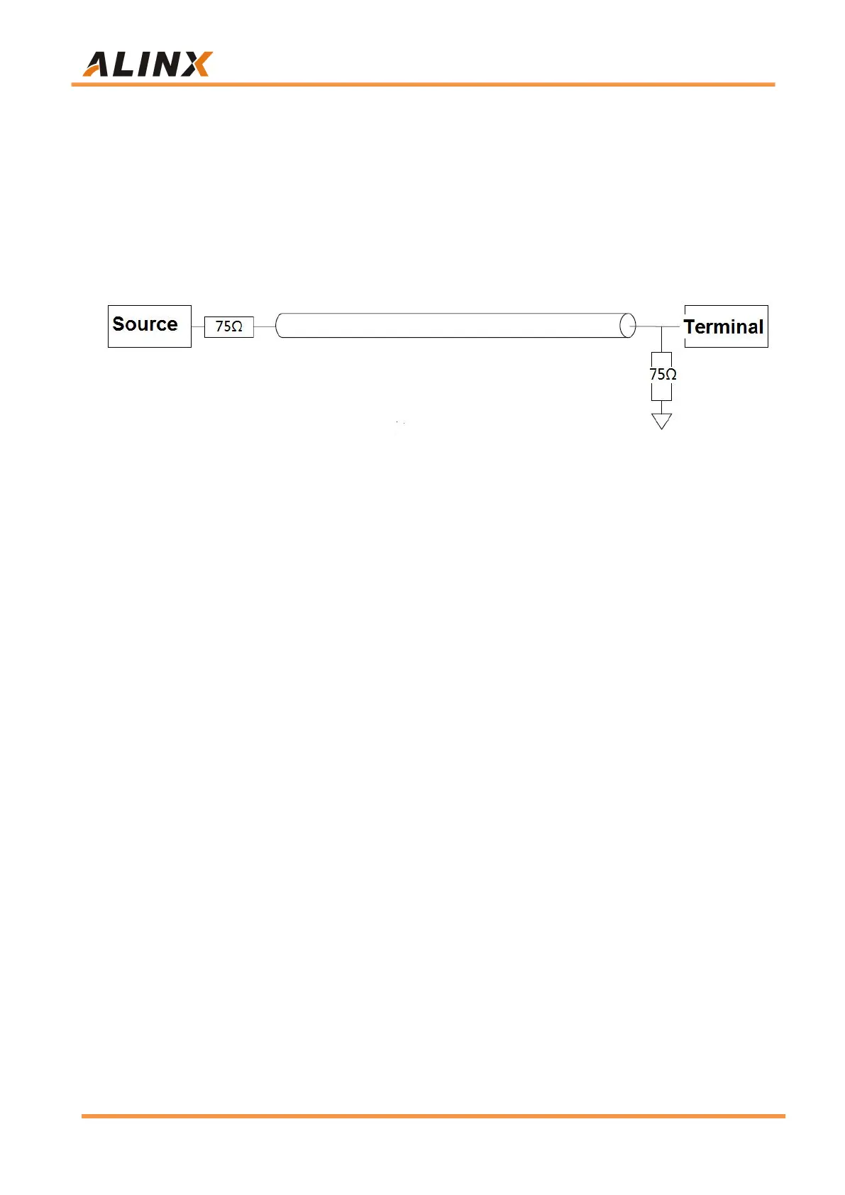
primary color source terminals and terminal matching resistors are both 75
ohms. Detail as Figure 3-4-1:
Figure 3-4-1: VGA Video Signal Transmission Diagram
HSYNC and VSYNC are line data synchronization and frame data
synchronization, respectively, which are TTL levels. The FPGA can only output
digital signals, while the R, G, and B required by the VGA are analog signals.
The digital to analog signal of the VGA is realized by a simple resistor circuit.
This resistor circuit can generate 32 gradient grade red and blue signals and 64
gradient grade green signals (RGB 5-6-5). The VGA interface part of the circuit
is shown in Figure 3-4-2.


 To Next Page