ZYNQ Ultrascale + FPGA Board AXU2CGA/B User Manual
Amazon Store: https://www.amazon.com/alinx
The Gigabit Ethernet pin assignments are as follows:
Transmit data Enable Signal
Receive Data Enable Signal
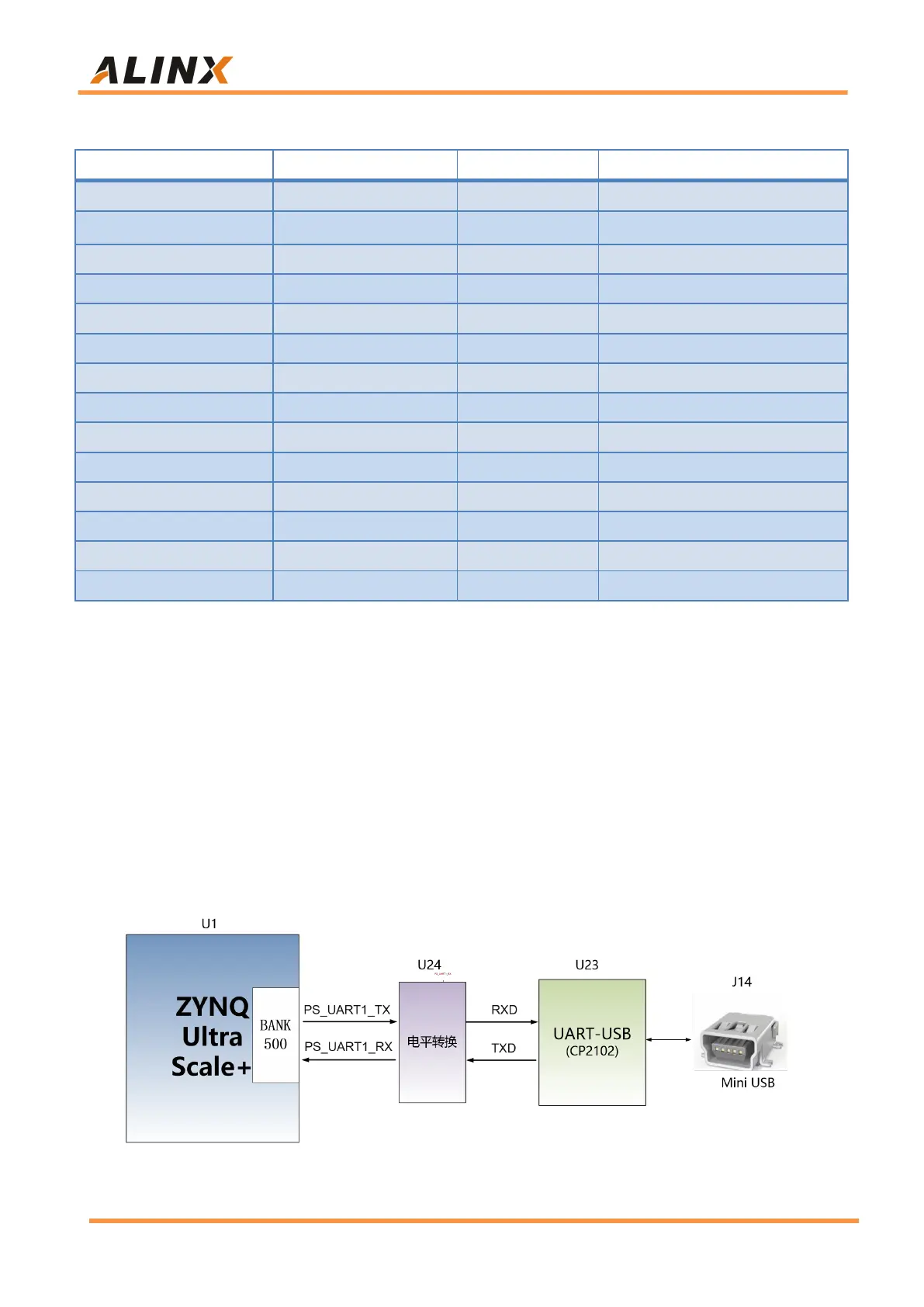
Part 10: USB to Serial Port
There is a Uart to USB interface on the AXU2CGA/B board for system
debugging. The conversion chip uses the USB-UAR chip of Silicon Labs
CP2102, and the USB interface uses the MINI USB interface. It can be
connected to the USB port of the PC with a USB cable for independent power
supply of the core board and serial data communication. The schematic
diagram of the USB Uart circuit design is shown in Figure 10-1:
Figure 10-1: USB to serial port schematic