EasyManua.ls Logo

Alinx AXU2CGA - Part 14: MIPI Camera Interface

Alinx AXU2CGA
29 pages
Print Icon
To Next Page IconTo Next Page
To Previous Page IconTo Previous Page
Loading...
ZYNQ Ultrascale + FPGA Board AXU2CGA/B User Manual
22 / 29
Amazon Store: https://www.amazon.com/alinx
31
IO2_15N
K12
32
IO2_15P
K13
33
IO2_16N
L13
34
IO2_16P
L14
35
IO2_17N
G10
36
IO2_17P
H11
37
GND
-
38
GND
-
39
VCC_3V3_BUCK4
-
40
VCC_3V3_BUCK4
-
Part 14: MIPI Camera Interface
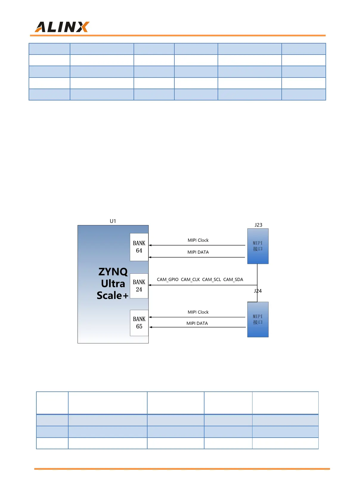
There are 2 MIPI interfaces on the AXU2CGA/B board for connecting MIPI
cameras. The differential signal of MIPI is connected to the HP IO of BANK64
and 65, and the level standard is +1.2V; the control signal of MIPI is connected
to BANK24, and the level standard is +3.3V. The schematic diagram of the
MIPI port design is shown in Figure 14-1:
Figure 14-1: MIPI Camera Interface Connection
MIPI Interface J23 Pin Assignment
PIN
Signal Name
ZYNQ Pin Name
ZYNQ Pin
Number
Description
1
GND
-
-
Ground
2
MIPI1_LAN0_N
IO_L2N_64
AE8
MIPI Data 0 Signal N
3
MIPI1_LAN0_P
IO_L2P_64
AE9
MIPI Data 0 Signal P

Related product manuals