General Pump
is a member of
the Interpump Group
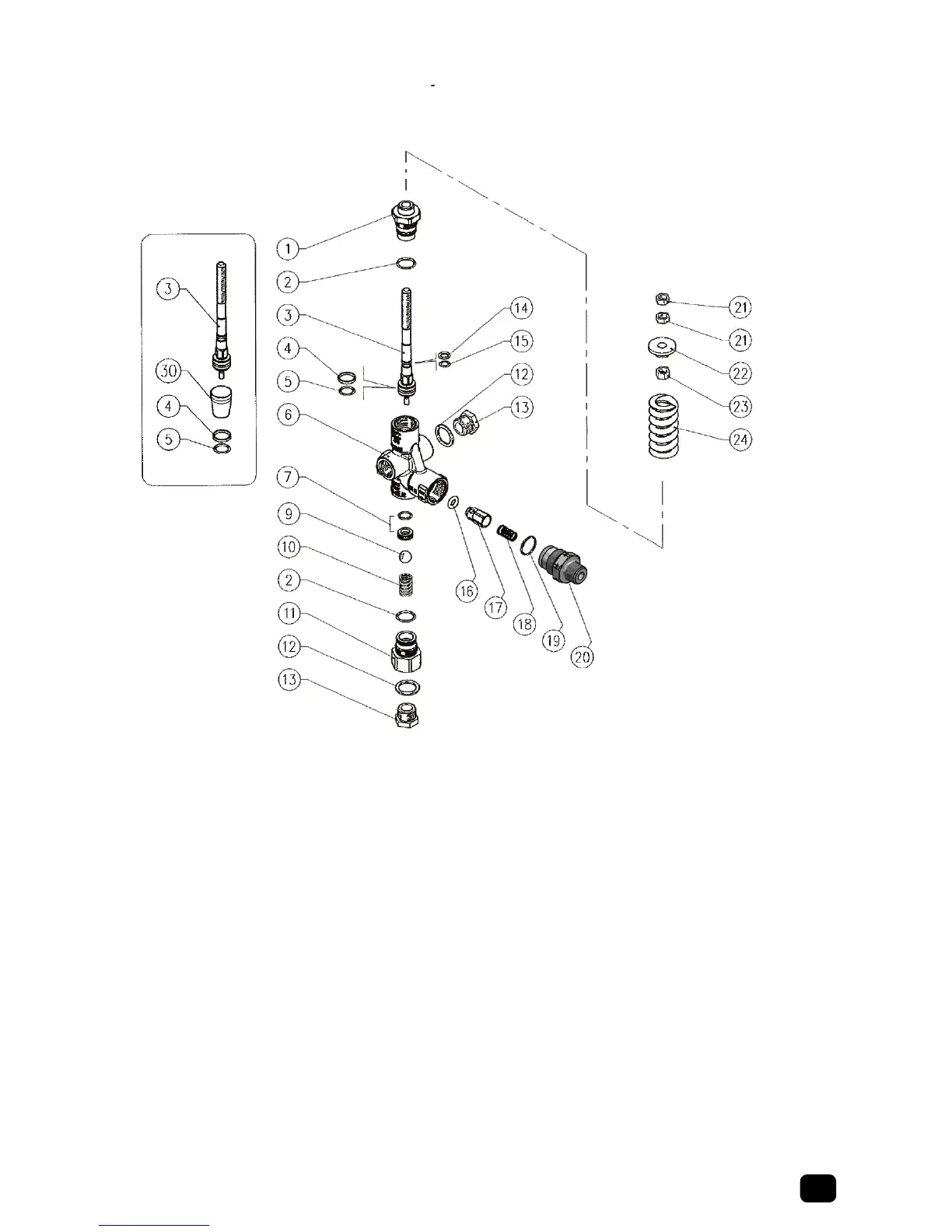
ITEM PART # DESCRIPTION QTY
1 Y60014631 Piston Holder, Brass 1
2* Y10306401 O-ring, 1.78x14mm 2
3 Y60002151 Piston, SST, R 1
4* Y10402100 Back-up Ring, 11.5x15.9x1.2mm 1
5* 701111 O-ring, 2.62x10.77mm 1
6 Y60013635 Housing, 3/8” NPT-F, Brass 1
7* Y60025920 Seat, 8mm + O-ring, 1.78mm 1
9* Y14746100 Ball, 13/32”, SST 1
10 Y60041051 Spring, 1.6x11.5x20mm, SST 1
11 Y60013731 Inlet Coupling, 3/8 NPT-F, Brass 1
13 Y60002531 Grub Screw, 3/8N
NPT 2
14* Y10400601 Back-up Ring, Opn, 6.2x9x1.2mm 1
15* Y10305101 O-ring, 1.78x6.07mm 1
16* Y10321300 O-ring, 3x6mm 2
17 Y60005299 Shutter Pin, Brass + O-ring 3x6mm 1
18 Y60005351 Spring, 0.7x9x20 SST 1
19* Y10306601 O-ring, 1.78x15.6mm, Ni 1
20 Y60103931 Nipple, 3/8 NPT-M 1
21 Y11457400 Hex Nut, M8 2
22 Y60001131 Spring Holder Ring, Brass 1
23 Y11457631 Hex Nut, M8, Brass 1
24 Y60003361 Spring, 5.7x26x53mm, Blue, PULSAR4HP 1
30 Y1044090
0 Seat Frame 1
* YKITPULSAR4 Spares Kit 1
General Pump
recommends using a
safety relief device in
conjunction with
this unloader valve
when installed on a
positive displacement
pump. General Pump is
not liable and assumes
no responsibility when
used in a customer’s
high pressure system.
Ref 300938 Rev. A
11-13
PART NUMBER PULSAR4HPM
Maximum Volume 10.5 GPM
Rated Pressure 4050 PSI
Maximum Pressure 4500 PSI
Maximum
Temperature
195
o
Note: The valve has been designed for continuous use at a water temperature of 140
o
F.
It can operate for short periods at a maximum temperature of 195
o
F.
Port Sizes Inlet (2) 3/8” NPT-F
Outlet 3/8” NPT-M
Bypass (2) 3/8” NPT-F
Overall Dimension 6.79” x 3.25” x 1.97”
Weight 1.5 Lbs.
UNLOADER PRESET AT FACTORY – DO NOT READJUST
Unloading Adjustment – Adjustment only after repair or replacement
1. Install an appropriate pressure gauge in pump head outlet. The gauge should
have a range twice the operating pressure.
2. Install the spray nozzle in the end of the wand.
3. Ensure the relief valve is set properly.
4. Loosen top lock nut (upper Item 21) and turn the nut (lower Item 21) counter
clockwise until minimum spring tension.
5. With machine turned on, open the trigger gun, start the pump, and observe
pressure gauge reading. Slowly loosen the
nut (lower Item 21) until pressure
starts to drop on the gauge.
6. Tighten adjusting nut (lower Item 21) on the unloader. Pressure should start to
increase. Tighten adjusting nut (lower Item 21) until pressure stops climbing.
7. Close and open the trigger gun to check unloading pressure and bypass function
of the unloader valve. The unloading pressure should not exceed operating
pressure more than 400 PSI.
8. Lock the setting by tightening the lock nut (upper Item 21).