Publication 1746-UM022B-EN-P - January 2005
4-4 Channel Configuration, Data, and Status
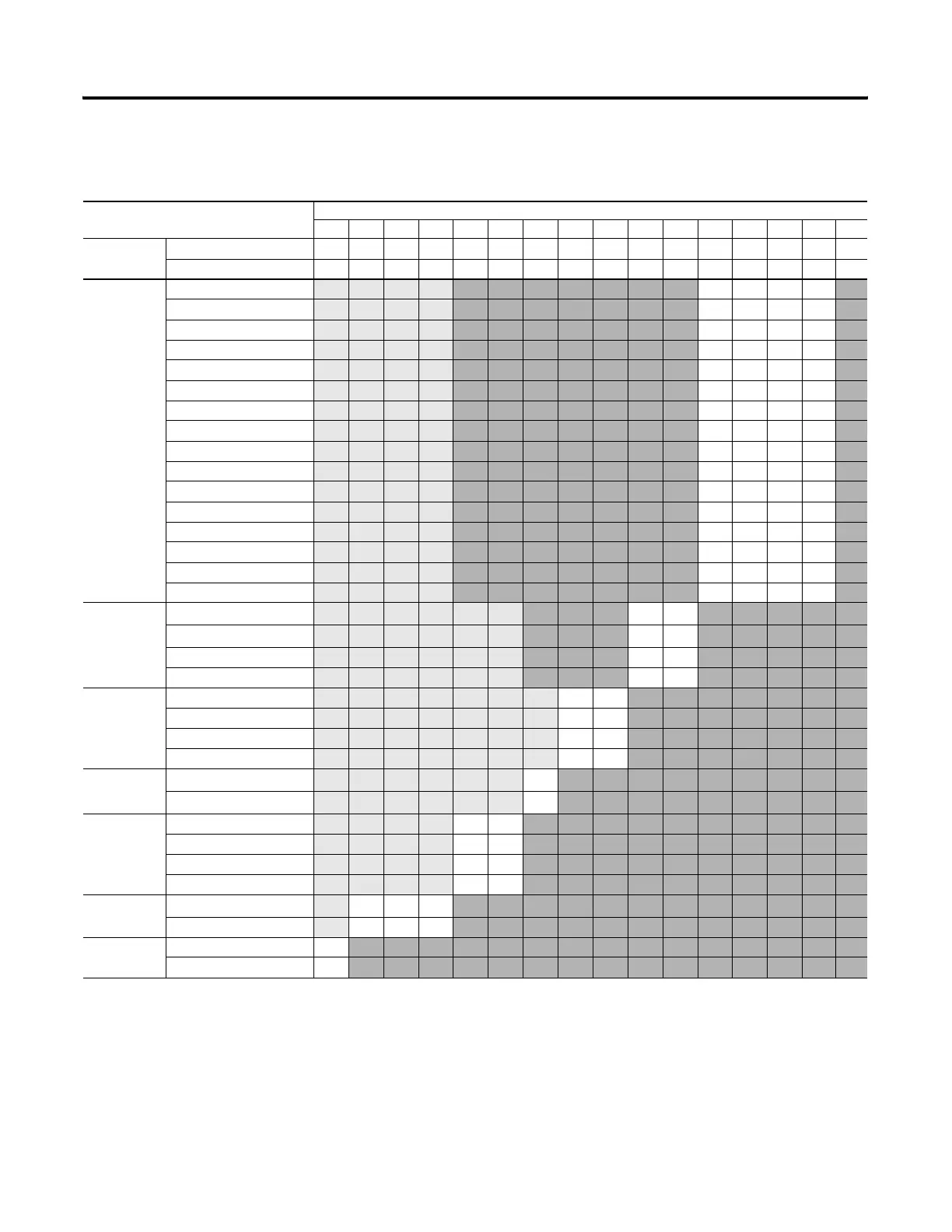
A detailed explanation appears in the following table:
Channel Configuration Word (0:e.0 through 0:e.7) - Bit Definitions
To Select Make these bit settings
1514131211109876543210
Channel
Enable
Channel Disable
0
Channel Enable
1
Input
Type
Thermocouple J
00
00
Thermocouple K 00
01
Thermocouple T 00
10
Thermocouple E 00
11
Thermocouple R 01
00
Thermocouple S 01
01
Thermocouple B 01
10
Thermocouple N 01
11
-50 to +50 mV 10
00
-100 to +100 mV 10
01
Invalid 10
10
Invalid 10
11
Invalid 11
00
Invalid 11
01
Invalid 11
10
CJC temperature 11
11
Data
Format
Engineering Units x 1
(1)
00
Engineering Units x 10
(1)
01
Scaled-for-PID
10
Proportional counts
11
Open Circuit
Zero on open circuit
00
Max. on open circuit
01
Min. on open circuit
10
Disabled
11
Temperature
units
°C
(2)
0
°F
(2)
1
Channel
filter
frequency
10 Hz input filter
00
50 Hz input filter
01
60 HZ input filter
10
250 Hz input filter
11
Unused
Unused
(3)
000
Invalid
111
Input Image
Type
Status Word
0
Data Word
1
(1) For engineering units x 1, values are expressed in 0.1 degrees or 0.01 mV. For engineering units x 10, values are expressed in 1.0 degrees or 0.1 mV.
(2) When millivolt input type is selected, the bit setting for temperature units is ignored.
(3) Ensure unused bits 12 through 14 are always set to zero.

 Loading...

