Publication 1747-UM006B-EN-P - June 2003
Quick Start for Experienced Users 2-5
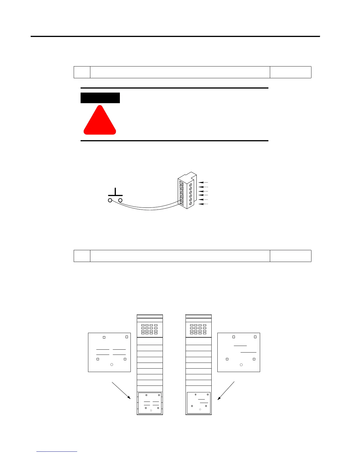
7. (Optional) Wire a processor restart lockout switch. Reference
Chapter 5
(Installation and
Wiring)
Use a momentary switch (Class 1, Division 2) to short terminals IN and RET together.
Important: Do not connect anything to the NC (No Connect) terminal.
ATTENTION
!
Cycling power on any 1747-ASB module chassis
removes the processor restart lockout condition
(SW-2) by reinitializing the 1747-ASB module.
Momentary Switch
14 to 24 gauge wire
(maximum 5 feet)
LINE 1 (Blue wire)
SHLD (Shield wire)
LINE 2 (Clear wire)
NC (No Connect)
IN
RET
8. Attach the appropriate I/O Module Addressing Labels. Reference
Attach the Remote PLC or Remote SLC label to the outside bottom of each I/O module in
your 1747-ASB chassis, as shown below. Fill out each label completely.
Chapter 5
(Installation and
Wiring)
Chapter 8
(Application
Examples)
BT Discrete
0 –7 8 – 15
SN Slot
SN Word(s)
Remote SLC System
Rack Group(s)
BT
Discrete
0 – 7 10 – 17 0 – 7 8 – 15
SN Slot
SN Word(s)
Remote PLC Label Remote SLC Label
INPUT INPUT
Remote PLC System
BT
Discrete
Remote SLC System
I:
O:
Rack Group(s)
Discrete
0 – 7 10 – 17
I:
O:
Remote PLC System
BT
R
R
R
R
Artisan Technology Group - Quality Instrumentation ... Guaranteed | (888) 88-SOURCE | www.artisantg.com

 Loading...


