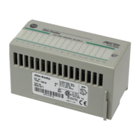
How to resolve illegal logical rack address on Allen-Bradley 1747-ASB?
- JJames BlakeSep 9, 2025
To correct an 'Illegal logical Rack Address' on your Allen-Bradley Control Unit, check the starting logical rack number (SW1-1,2,3,4,5,6).

How to resolve illegal logical rack address on Allen-Bradley 1747-ASB?
To correct an 'Illegal logical Rack Address' on your Allen-Bradley Control Unit, check the starting logical rack number (SW1-1,2,3,4,5,6).
How to fix 1747-ASB module image size too large on Allen-Bradley Control Unit?
To resolve the '1747-ASB Module Image Size Too Large' error on your Allen-Bradley Control Unit, check the image size selection (SW2-5,6,7,8). Note that 16 logical groups is the maximum size when 2-slot addressing is selected.
What to do if Allen-Bradley Control Unit shows remote power fail?
If your Allen-Bradley Control Unit displays 'Remote Power Fail (expansion chassis powered down)', ensure that power is supplied to all remote expansion chassis and inspect the remote expansion cable connections.
How to fix last address exceeded error on Allen-Bradley Control Unit?
To address the 'Last Address Exceeded' error on your Allen-Bradley Control Unit, check the starting logical rack number (SW1-1,2,3,4,5,6), starting logical group number (SW1-7,8), and image size selection (SW2-5,6,7,8).
How to resolve DIP switch configuration mismatch on Allen-Bradley Control Unit?
If your Allen-Bradley Control Unit indicates 'DIP Switch Configuration Mismatch', either correct the incorrect switch settings or change to Save Mode.
How to resolve I/O configuration mismatch on Allen-Bradley 1747-ASB?
If your Allen-Bradley Control Unit displays 'I/O Configuration Mismatch and Location' due to a problem with a specific slot, correct the I/O module configuration problem or change to Save Mode.
What to do if Allen-Bradley Control Unit detects Watchdog Reset?
If your Allen-Bradley Control Unit detects a Watchdog Reset, cycle the power to reset the 1747-ASB module. If the issue persists, replace the 1747-ASB module.
What to do if Allen-Bradley 1747-ASB displays last chassis not allowed?
If your Allen-Bradley Control Unit displays 'Last Chassis Not Allowed', check primary/complementary chassis selection (SW2-3), and the last chassis selection (SW3-4).
What to do if Allen-Bradley 1747-ASB indicates bad number of chassis?
If your Allen-Bradley Control Unit indicates 'Bad Number of chassis', remove the extra chassis.
What to do if Allen-Bradley Control Unit displays Configuration Read Fault?
If your Allen-Bradley Control Unit displays 'Configuration Read Fault (data in EEPROM not valid)', change to Save Mode and restore power. Then, change back to Check Mode and restore power.
| Model | 1747-ASB |
|---|---|
| Category | Control Unit |
| Manufacturer | Allen-Bradley |
| Series | SLC 500 |
| Communication Protocol | Remote I/O |
| Power Supply | 24V DC |
| Compatibility | SLC 500 |
| Current Draw | 0.5 A |
| Operating Temperature | 0 to 60 °C |
| Storage Temperature | -40°C to 85°C |
| Relative Humidity | 5 to 95% (non-condensing) |
| Product Type | Remote I/O Adapter Module |
Identifies the intended audience for the manual based on their responsibilities.
Explains the manual's objective and content for the remote I/O adapter module.
Defines key technical terms and abbreviations used throughout the manual.
Provides a general description of the 1747-ASB module and its role in RIO communication.
Explains the concept and operation of Remote I/O systems and communication.
Highlights the physical components, LEDs, and DIP switches of the 1747-ASB module.
Describes the different types of chassis available for remote I/O systems.
Details the slot numbering scheme within chassis for module placement and addressing.
Explains the configuration where two chassis slots are addressed as one logical group.
Details the function and settings of the module's three DIP switches for configuration.
Configures the communication speed for the module on the RIO link.
Determines the size of the module's image reserved in the scanner.
Provides step-by-step instructions for physically installing the module into the chassis.
Guides on connecting network devices in a daisy chain configuration using Belden 9463 cable.
Explains the correct use of terminating resistors for RIO link integrity and baud rates.
Outlines the procedure for initial system startup and module verification.
Describes the module's behavior and indicators during normal system operation.
Explains conditions that may prevent normal RIO link communications.
Introduces troubleshooting concepts, module indicators, and error types.
Lists error codes, their meanings, and corrective actions for module faults.
Details fault codes related to incorrect DIP switch settings and their meanings.
Illustrates a practical application using an SLC 500 processor and RIO scanner.
Shows the input and output image structure for an SLC processor in the example.
Provides examples of how to fill out RIO address labels for module identification.
Lists the operational parameters and environmental limits for the adapter module.
Details baud rate, cable length, and resistor specifications for network setup.
Explains the process and formulas for calculating system throughput.
Compares the hold last state functionality between the two module series.
Explains differences in mapping and controlling specialty I/O modules.
Highlights differences in physical slot numbering conventions between the modules.
Provides a template for recording DIP switch settings for module configuration.
Offers a worksheet to document the I/O module addressing within the chassis.


 Loading...