16 Rockwell Automation Publication 1756-UM058G-EN-P - November 2012
Chapter 1 What Are ControlLogix Digital I/O Modules?
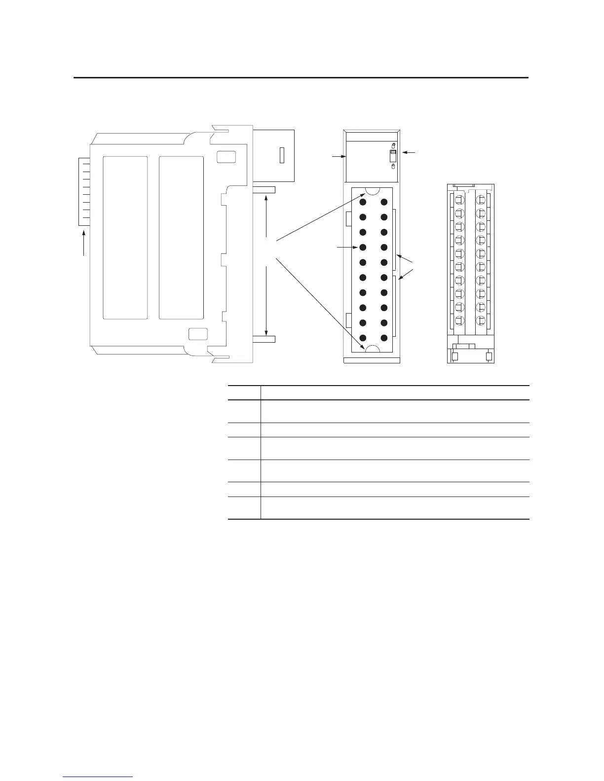
Figure 1 - Parts Illustration
40200-M
DC OUTPUT
ST
O
K
01
2
34567
3
5
Removable Terminal Block
6
4
2
1
Item Description
1 Backplane Connector—Interface for the ControlLogix system that connects the module to the
backplane.
2 Top and bottom guides—Guides provide assistance in seating the RTB or IFM onto the module.
3 Status indicators—Indicators display the status of communication, module health, and input/output
devices. Indicators help in troubleshooting anomalies.
4 Connector pins—Input/output, power, and grounding connections are made to the module through
these pins with the use of an RTB or IFM.
5 Locking tab—The locking tab anchors the RTB or IFM on the module, maintaining wiring connections.
6 Slots for keying—Mechanically keys the RTB to prevent making the wrong wire connections to your
module.
 Loading...


