Rockwell Automation Publication 1756-UM058G-EN-P - November 2012 177
Appendix A
Troubleshoot Your Module
This appendix describes the status indicators on the ControlLogix digital
modules and how to use them to troubleshoot the module. Each I/O module has
status indicators located on the front of the module.
Status Indicators
for Input Modules
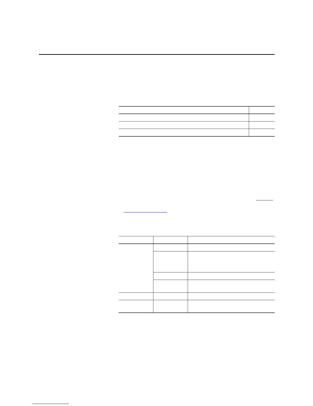
ControlLogix input modules support the status indicators described in Tab l e 3 1
below. The available status indicators vary by module catalog number, as shown
in Figure 21 on page 178
.
Topic Page
Status Indicators for Input Modules 177
Status Indicators for Output Modules 178
Use RSLogix 5000 Software for Troubleshooting 180
Table 31 - Status Indicators for Input Modules
Indicator Status Description
OK Status Steady green The inputs are being multicast and in a normal operating state.
Flashing green The module has passed internal diagnostics, but is not
multicasting inputs or is inhibited.
Uninhibit the connection or establish a connection to enable
communication to the module.
Steady red The module must be replaced.
Flashing red Previously established communication has timed out.
Check the controller and chassis communication.
I/O Status Yellow The input is On.
Fault Status Red The input has encountered a fault.
Check the input point at the controller.
 Loading...


