64 Rockwell Automation Publication 1756-UM058G-EN-P - November 2012
Chapter 3 Common Module Features
Use the Module Properties dialog box in RSLogix 5000 software to determine if
the module has been synchronized with the owner-controller and whether the
controller is synchronized with the CST. For more information on synchronizing
owner-controllers and modules with the CST, see the ControlLogix System User
Manual, publication 1756-UM001
.
Fault and Status Reporting
between Input Modules and
Controllers
ControlLogix digital input modules multicast fault and status data to any owner-
controller or listening controller. All input modules maintain a module-fault
word, the highest level of fault reporting.
The table lists the fault word and the associated tag that can be examined in
program logic to indicate when a fault has occurred for a standard input module.
All words are 32-bit, although only the number of bits appropriate for each
module’s density are used. For example, the 1756-IA16I module has a module-
fault word of 32 bits. But, because this is a 16-point module, only 16 bits (0…15)
are used in the module-fault word.
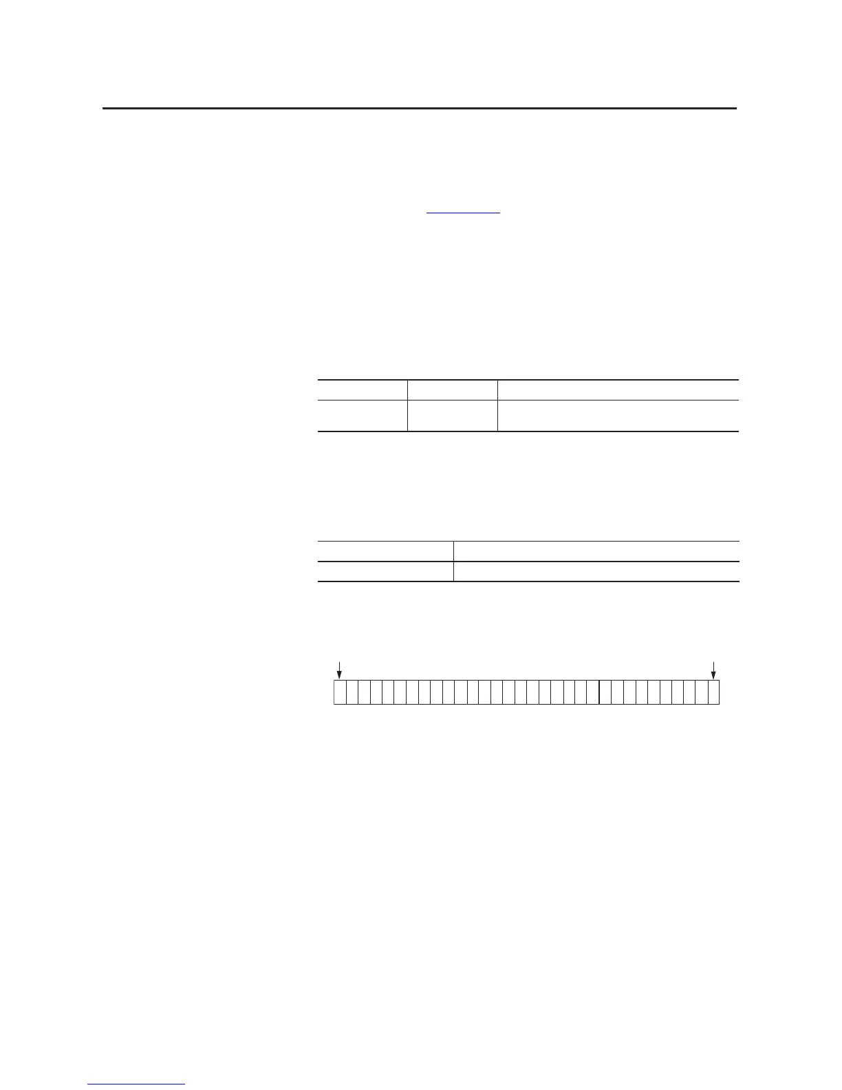
The following illustration offers an overview of the fault reporting process on
ControlLogix standard digital input modules.
Table 4 - Fault Word on Input Modules
Word Tag Name Description
Module-fault Fault Provides fault summary reporting. Available on all digital input
modules.
Table 5 - Bits Set in Module-fault Word
Condition Bits Set
Communication fault All 32 bits are set to 1, regardless of the module’s density.
 Loading...


