226 Rockwell Automation Publication 1756-UM058G-EN-P - November 2012
Appendix C Use Ladder Logic To Perform Run Time Services and Reconfiguration
The input point (point 0) must have Change of State enabled. Otherwise,
the timestamp will not update when the point transitions.
Once Change of State has been detected, the value in the Delay tag is
added to the input timestamp and sent to the output module's timestamp
using a COP instruction. This causes the output module to apply its
output at a time equal to the time that the input changed state plus the
Delay time.
The final COP instruction updates LastInputTimestamp in preparation
for the next change of state.
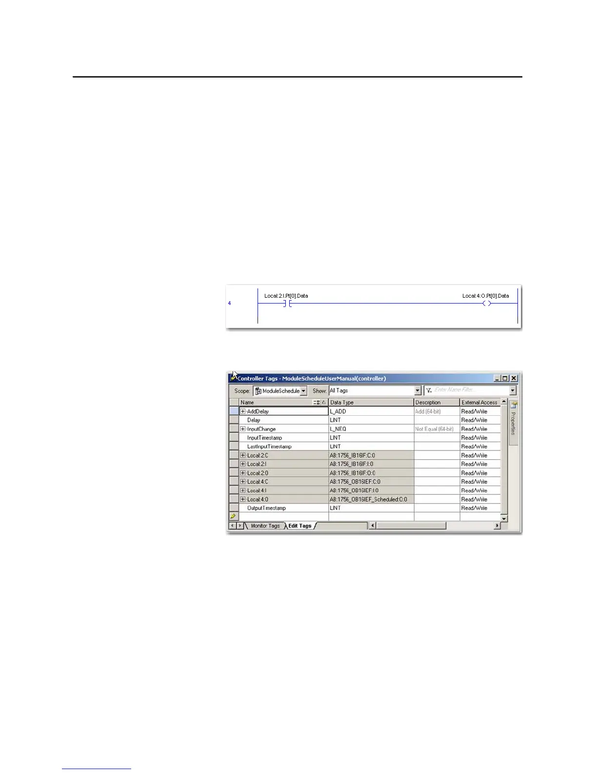
• Rung 4 is the standard XIC-OTE rung that controls the output point
based on the input point. The only difference is that the output module is
configured for scheduled outputs. The outputs will not get applied until
the scheduled time has occurred.
The Controller Tags dialog box below shows examples of the tags created in
ladder logic.
 Loading...


