Rockwell Automation Publication 1756-RM093J-EN-P - April 2018 21
Chapter 2
GuardLogix Controller System
For a brief listing of components suitable for use in Safety Integrity Level (SIL) 3
applications, see the table on page
14. For more detailed and up-to-date
information see http://www.rockwellautomation.com/products/certification/
safety/.
When installing a GuardLogix® controller, follow the information in the
GuardLogix Controllers User Manual, publication 1756-UM020
, or
CompactLogix™ Controllers Installation Instructions, publication 1768-IN004
.
1756 GuardLogix Controller
Hardware
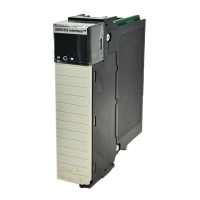
The 1756 GuardLogix controller consists of a primary controller
(ControlLogix® 556xS) and a safety partner (ControlLogix 55SP). These two
modules work in a 1oo2 architecture to create the SIL 3-capable controller. They
are described in the following sections.
Both the primary controller and safety partner perform power-up and run-time
functional diagnostic tests of all safety-related components in the controller.
For details on status indicator operation, refer to the GuardLogix Controllers
User Manual, publication 1756-UM020
.
For a list of GuardLogix safety controller catalog numbers see Ta ble 2 on pag e 14
.
For a list of standard ControlLogix components suitable for safety applications,
see Table 3 on p a g e 14
.
Topic Page
1756 GuardLogix Controller Hardware 21
1768 Compact GuardLogix Controller Hardware 23
CIP Safety Protocol 23
Safety I/O 23
Communication Bridges 24
Programming Overview 26
Status indicators are not reliable indicators for safety functions. They should
be used only for general diagnostics during commissioning or
troubleshooting. Do not attempt to use status indicators to determine
operational status.

 Loading...


