Publication 2100-IN012B-EN-P - April 2005
4-4 Installing Conduit and Cable
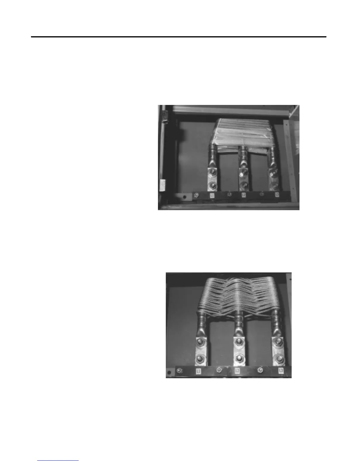
In Figure 4.1, glass fiber reinforced tape or glass filament tape is used. The
taping should be continuous from the point the cables enter the MCC to the
point the cables are terminated. It is important that cables are wrapped several
times for additional strength. Cable slack should be drawn up during wrapping
so that individual cables are supported by the tape as a single mass.
Figure 4.1 Securing Cables with Glass Tape
In Figure 4.2, cables are lashed in a “figure 8”-type configuration using nylon
rope. The rope lashing should be continuous from the point the cables enter
the MCC to the point the cables are terminated. Other types of rope lashing
may be acceptable. Cable slack should be drawn up during wrapping so that
individual cables are supported by the rope as a single mass.
Figure 4.2 Securing Cables with Nylon Rope
 Loading...


