Publication 2100-IN012B-EN-P - April 2005
2-6 Installation Procedures
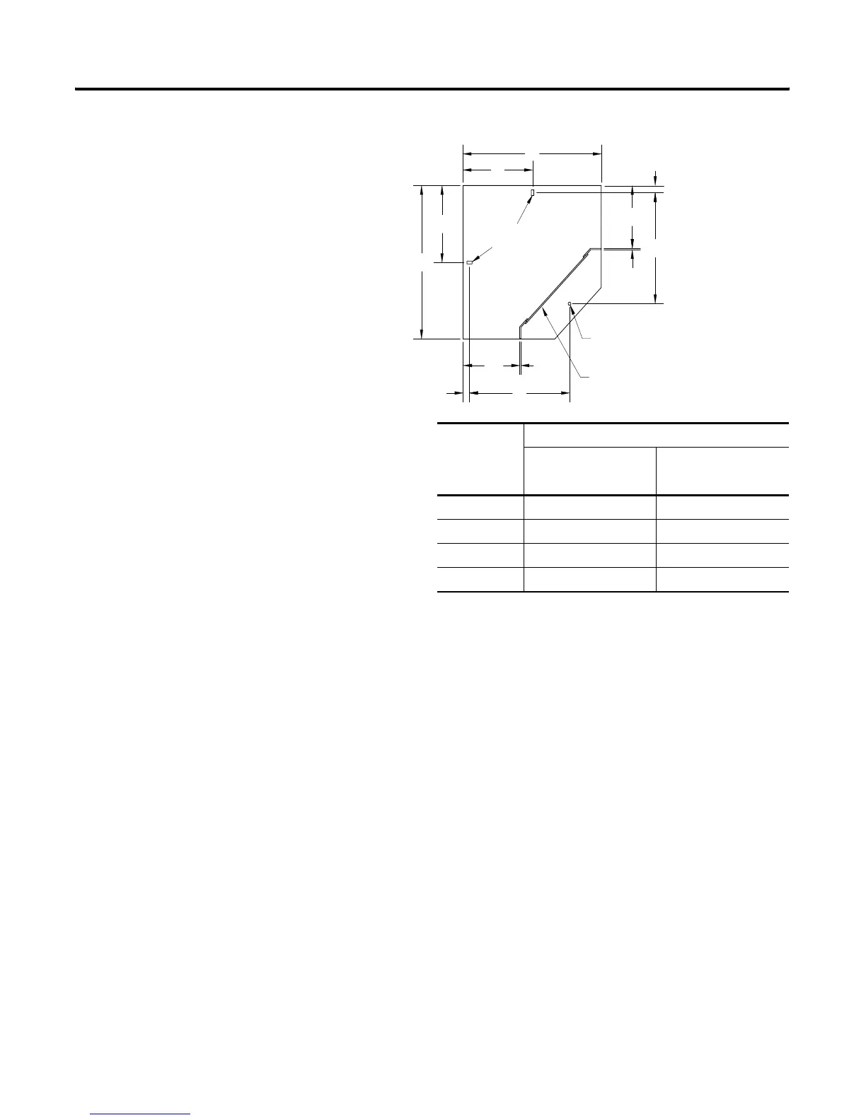
Figure 2.6 Mounting Dimensions for 15” and 20” Deep Corner Section
NOTE: Documentation packages shipped with assembled MCCs include an
MCC elevation drawing showing an MCC floor plan layout.
Seismic Requirements
To demonstrate the seismic withstand of various CENTERLINE Motor
Control Centers (15” deep [380 mm], 20” deep [508 mm], 30” deep [762 mm]
back-to-back and 40” deep [1016 mm] back-to-back), the MCC design
construction has been qualified by seismic calculations per the Uniform
Building Code (UBC). The CENTERLINE seismic withstand has been
qualified by subjecting MCC samples to static and dynamic (triaxial
multi-frequency testing) seismic tests. The results of this evaluation and testing
qualify the CENTERLINE MCC of sufficient integrity to exceed a Zone 4
seismic withstand per the UBC's requirements, i.e. neither the MCC structure,
units, components or electrical functions will be compromised when subjected
to a Zone 4 seismic event.
NOTE: Zone 4 is the maximum UBC seismic magnitude.
To obtain a UBC Zone 4 seismic withstand rating, each CENTERLINE MCC
line-up (i.e., both front and back MCCs in back-to-back applications) must be
mounted on an adequate seismic foundation and installed per the seismic
anchoring requirements. See Figure 2.7 for bolt down dimensions. See Figure
2.8 for weld down securing.
Section Depth
Dimension 15” (381mm) Deep 20” (635mm) Deep
in (mm) in (mm)
A 25.13 (638) 30.13 (765)
B 12.63 (321) 15.13 (384)
C 16.81 (427) 21.81 (554)
D 17.62 (448) 22.62 (575)
(1) Mounting Holes
.63" (16mm) diameter
A
B
C
1.41" (3.58mm)
C
D
.25" (6mm)
.25" (6mm)
D
1.41" (36mm)
(2) Mounting Slots
.56" X 1.13" Slot
(14mm) X (29mm) slot
B
A
Ground Bus
 Loading...


