EasyManuals Logo

Allen-Bradley CENTERLINE User Manual

Allen-Bradley CENTERLINE
88 pages
To Next Page IconTo Next Page
To Previous Page IconTo Previous Page
Page #22 background imageLoading...
Page #22 background image
Publication 2100-IN012B-EN-P - April 2005
2-2 Installation Procedures
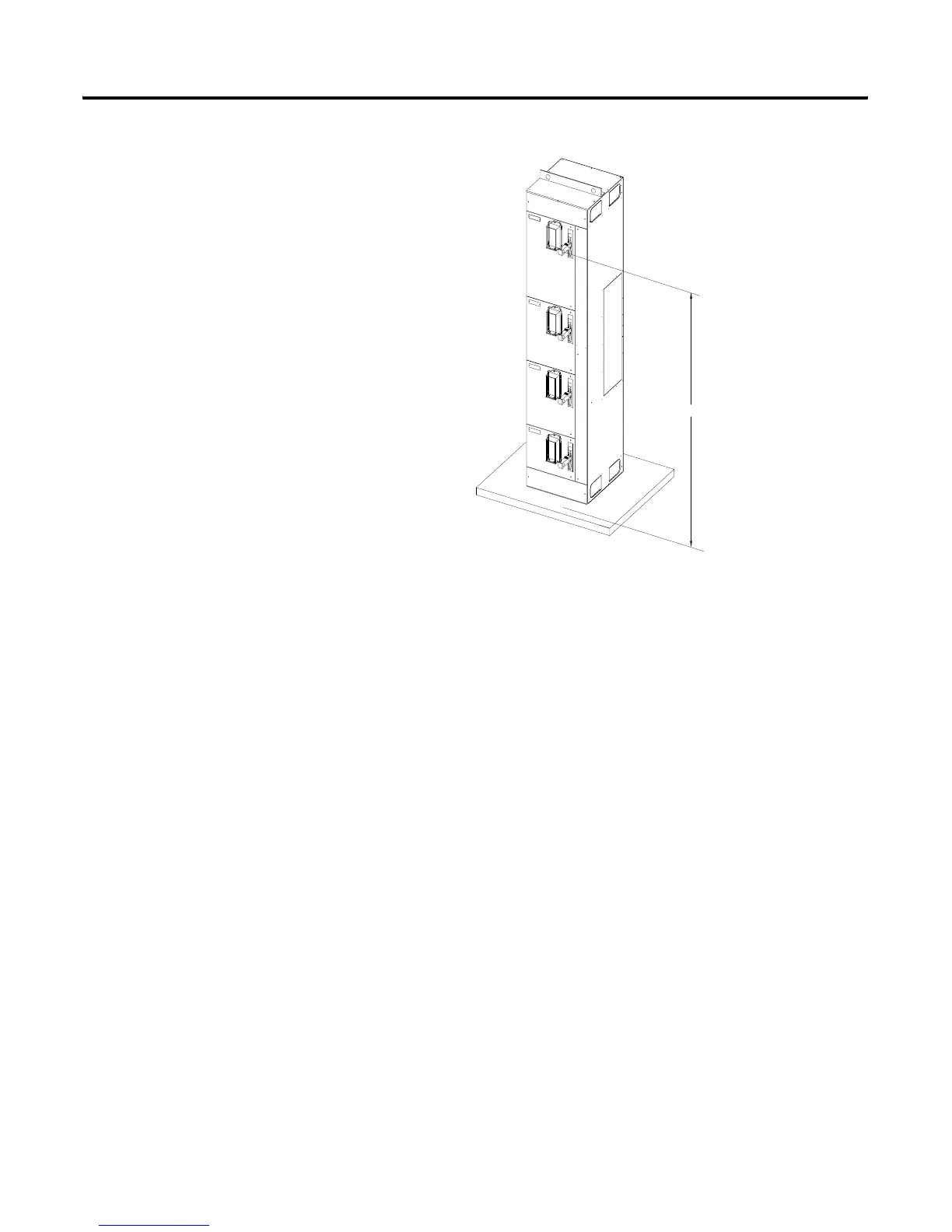
Figure 2.1 Height Planning Dimensions
Securing a Motor Control
Center
Anchor bolts (1/2” [13 mm]) may be pre-located and embedded in the
foundation prior to installation. Two bolts per vertical section fasten the motor
control center through its internal mounting angle to the foundation (corner
sections require three bolts and 40” [1016 mm] wide sections require four
bolts). See Figure 2.2 through Figure 2.6 for general dimensions. Dimensions
matching your equipment can be found on the elevation drawings shipped
with your MCC.
HEIGHT OF
HANDLE
6' 7" MAX
FLOOR LINE
CEMENT PAD

Table of Contents

Questions and Answers:

Question and Answer IconNeed help?

Do you have a question about the Allen-Bradley CENTERLINE and is the answer not in the manual?

Allen-Bradley CENTERLINE Specifications

General IconGeneral
Short Circuit Current Rating (SCCR)Up to 100kA
Modular DesignYes
TypeMotor Control Center (MCC)
VoltageUp to 600V AC
Communication ProtocolsEtherNet/IP, DeviceNet
Enclosure TypeNEMA 1, NEMA 3R, NEMA 4, NEMA 4X, NEMA 12
Standards ComplianceUL 845, IEC 61439

Related product manuals