Publication 2100-IN012B-EN-P - April 2005
Installation Procedures 2-3
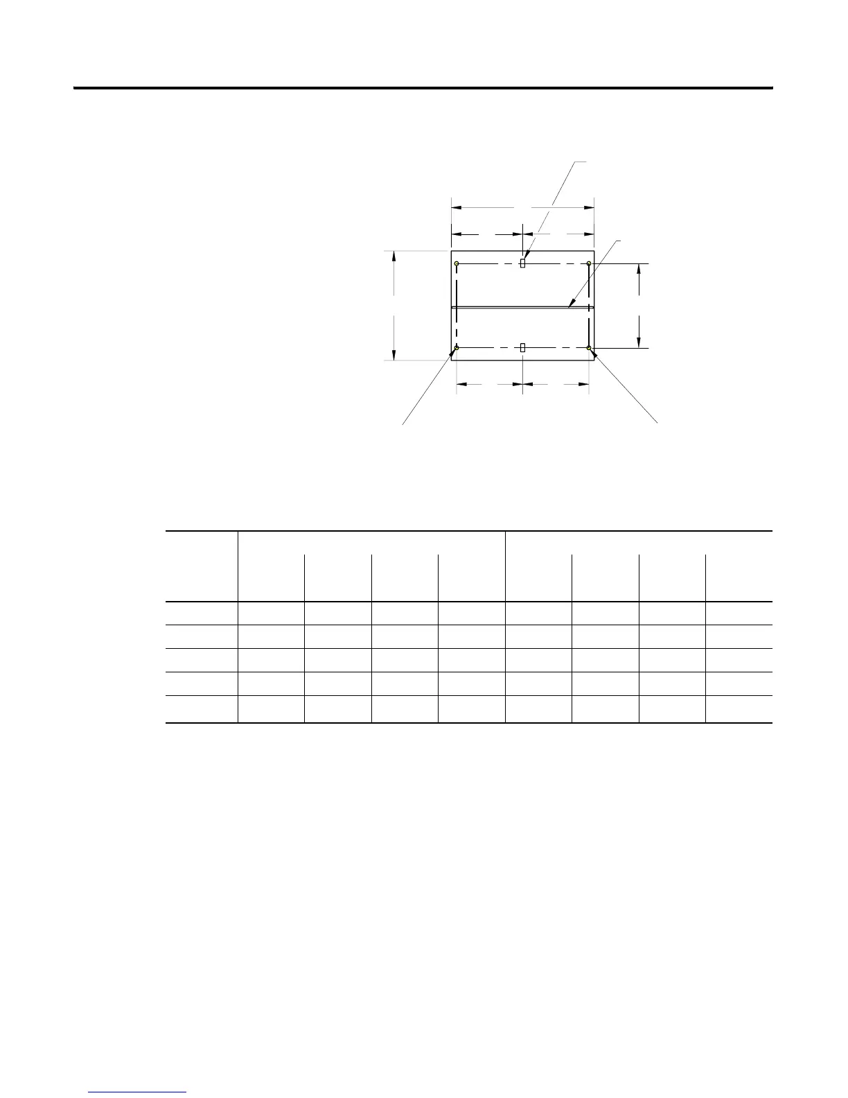
Figure 2.2 Mounting Dimensions for 15” and 20” Deep Front-Mounted Section
For Seismic bolt-down applications:
First section of the MCC line-up
For Seismic bolt-down applications:
Last section of the MCC line-up
extra bolt-down locations (2 bolts)
(2) mounting slots
.56" x 1.13" SLOTS
(14mm) x (29mm) SLOTS
Ground Bus
D
D
A
E
E
B
C
Front
Rear
Dimension
15" Deep 20" Deep
20" Wide 25" Wide 30" Wide 35" Wide 20" Wide 25" Wide 30" Wide 35" Wide
in (mm) in (mm) in (mm) in (mm) in (mm) in (mm) in (mm) in (mm)
A 20.00 (508) 25.00 (635) 30.00 (762) 35.00 (889) 20.00 (508) 25.00 (635) 30.00 (762) 35.00 (889)
B 15.00 (381) 15.00 (381) 15.00 (381) 15.00 (381) 20.00 (508) 20.00 (508) 20.00 (508) 20.00 (508)
C 11.56 (294) 11.56 (294) 11.56 (294) 11.56 (294) 16.56 (421) 16.56 (421) 16.56 (421) 16.56 (421)
D 10.00 (254) 12.50 (318) 15.00 (381) 17.50 (445) 10.00 (254) 12.50 (318) 15.00 (381) 17.50 (445)
E
(1)
9.25 (235) 11.75 (298) 16.75 (425) 19.25 (489) 9.25 (235) 11.75 (298) 16.75 (425) 19.25 (489)
(1)
Applies to first and last sections that require seismic ratings.
 Loading...


