Publication 2100-IN012B-EN-P - April 2005
2-4 Installation Procedures
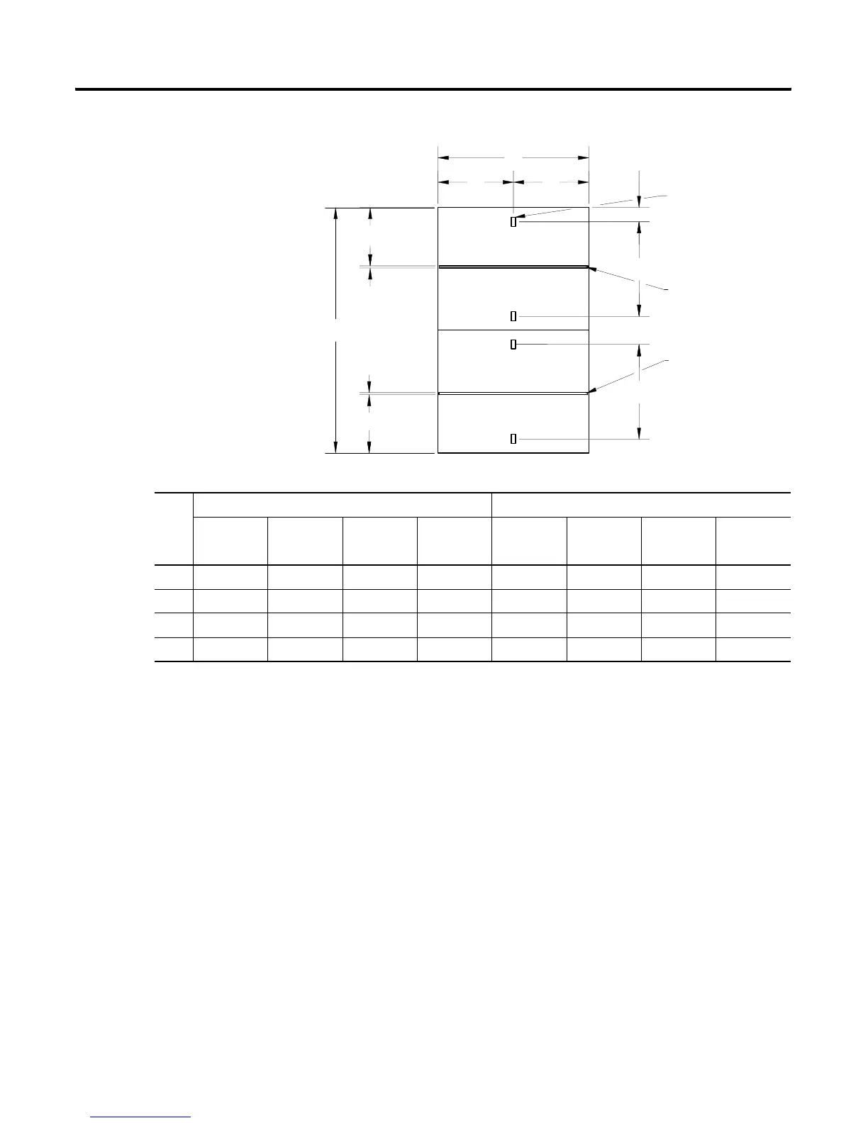
Figure 2.3 Mounting Dimensions for 30” and 40” Deep Back-to-Back Section
7.38" (187mm)
7.38" (187mm)
.25" (6mm)
.25" (6mm)
B
A
1.69" (43mm)
(4) Mounting Slots
.56" x 1.13" Slots
(14mm) x (29mm) Slots
Standard Ground Bus
3.19" (81mm)
C
Standard Ground Bus
C
Front
Front
Rear
Rear
D
D
20” Deep 40” Deep
20” Wide 25” Wide 30” Wide 35” Wide 20” Wide 25” Wide 30” Wide 35” Wide
in (mm) in (mm) in (mm) in (mm) in (mm) in (mm) in (mm) in (mm)
A 20.00 (508) 25.00 (635) 30.00 (762) 35.00 (889) 20.00 (508) 25.00 (635) 30.00 (762) 35.00 (889)
B 30.00 (762) 30.00 (762) 30.00 (762) 30.00 (762) 40.00 (1016) 40.00 (1016) 40.00 (1016) 40.00 (1016)
C 11.56 (294) 11.56 (294) 11.56 (294) 11.56 (294) 16.56 (421) 16.56 (421) 16.56 (421) 16.56 (421)
D 10.00 (254) 12.50 (318) 15.00 (381) 17.50 (445) 10.00 (254) 12.50 (318) 15.00 (381) 17.50 (445)
 Loading...


