Publication 2100-IN012B-EN-P - April 2005
5-6 Installing and Removing Plug-In Units
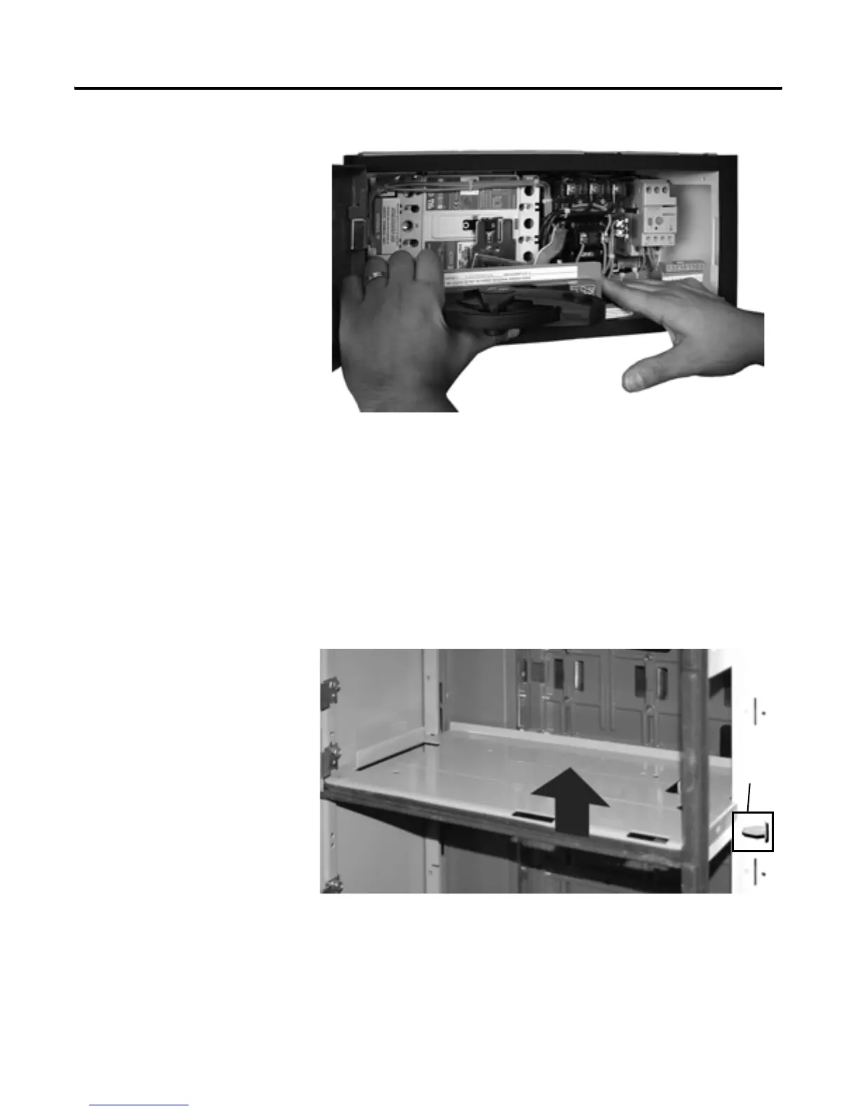
Figure 5-9 Removing a Unit with a Horizontal Operating Handle
10. Push latch mechanism to the left with right hand.
11. Pull unit forward (outward) with left hand using the left top portion of
the disconnect handle flange as finger hold.
12. Carefully install protective caps or close manual shutters after unit is
removed. See Figure 5-11.
Automatic shutters will close as units are removed.
Removing Support Pan
Figure 5-10 Removing the Unit Support Pan
1. Pry the plastic retaining clip from the right hand unit support using a
screwdriver. This is visible in the vertical wireway.
2. Lift the right side of the support pan approximately 4” (102mm).
Plastic
Retaining
Clip
 Loading...


