EasyManuals Logo

Allen-Bradley CENTERLINE User Manual

Allen-Bradley CENTERLINE
88 pages
To Next Page IconTo Next Page
To Previous Page IconTo Previous Page
Page #53 background imageLoading...
Page #53 background image
Publication 2100-IN012B-EN-P - April 2005
Installing and Removing Plug-In Units 5-5
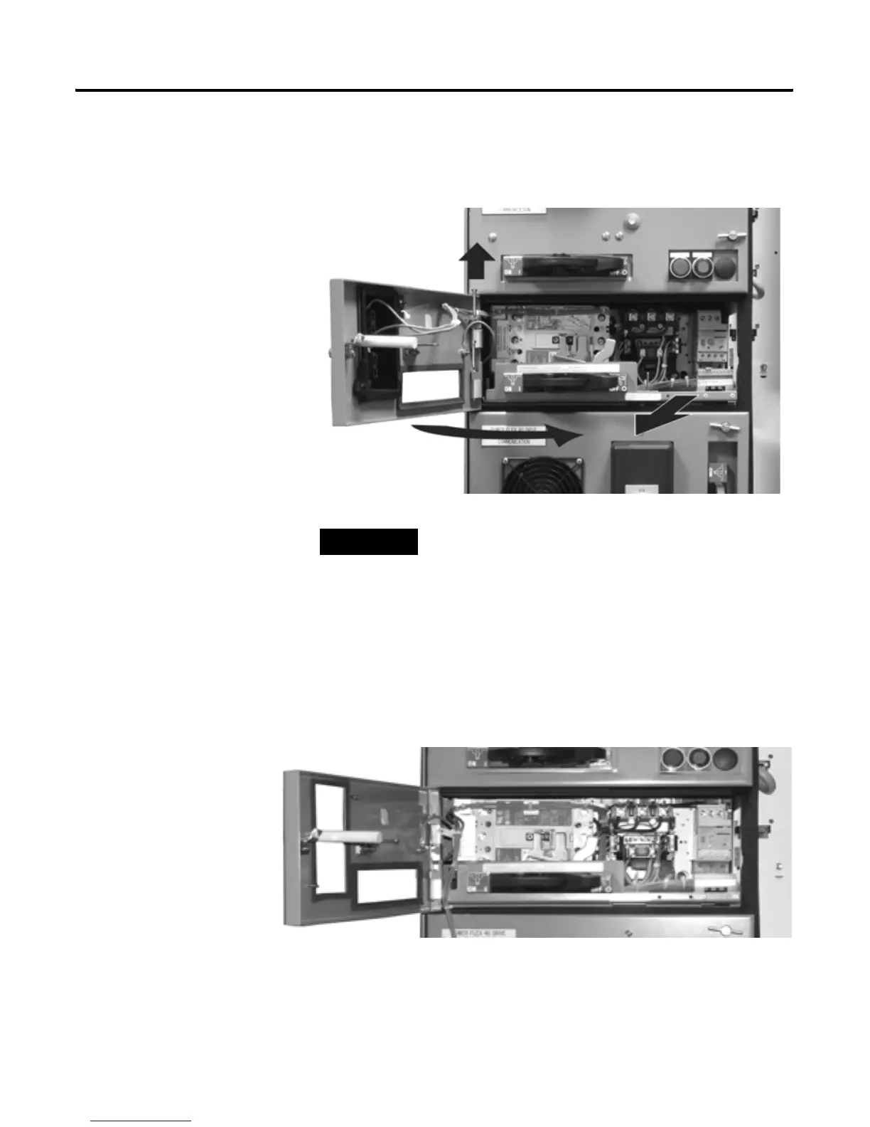
2. Turn door latch 1/4 turn.
3. Open door completely.
Figure 5-7 Removing a Unit with a Horizontal Operating Handle.
4. Remove door-mounted devices and/or wiring, if necessary.
5. Remove hinge pins by sliding upward with a flathead screwdriver.
6. Swing door to near closed position.
7. Lift door outward to remove.
Figure 5-8 Unit with a Horizontal Operating Handle with Control Station Removed
8. Detach wiring/terminal block from unit.
9. Place wiring/terminal block in vertical wireway to right of unit.
TIP
It not necessary to remove the unit door in order to
remove a unit from a section.

Table of Contents

Questions and Answers:

Question and Answer IconNeed help?

Do you have a question about the Allen-Bradley CENTERLINE and is the answer not in the manual?

Allen-Bradley CENTERLINE Specifications

General IconGeneral
Short Circuit Current Rating (SCCR)Up to 100kA
Modular DesignYes
TypeMotor Control Center (MCC)
VoltageUp to 600V AC
Communication ProtocolsEtherNet/IP, DeviceNet
Enclosure TypeNEMA 1, NEMA 3R, NEMA 4, NEMA 4X, NEMA 12
Standards ComplianceUL 845, IEC 61439

Related product manuals