Publication 2100-IN012B-EN-P - April 2005
Installation Procedures 2-7
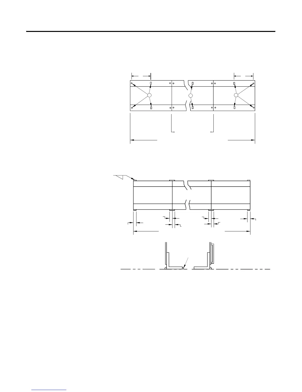
NOTE: In seismic application dimensions “E” applies to the first and last
sections of the MCC line-up. See Figure 2.2 for dimensions.
Figure 2.7 Seismic Bolt Down Requirements
Figure 2.8 Seismic Weld Down Requirements
Joining & Splicing New
Motor Control Centers
A main horizontal bus splice kit must be installed between shipping blocks of
new motor control centers to connect the main horizontal bus. In addition, the
neutral bus splice kit (if required) and the ground bus splice kit must be
installed between shipping blocks. Refer to 2100-IN010x-EN-P - Joining &
Splicing Vertical Sections.
- HARDWARE REQUIRED IS 1/2 INCH GRADE 2
OR BETTER BOLTS EMBEDDED IN FOUNDATION
REAR
FRONT
FIRST SECTION
2ND SECTION AND
ADDITONAL SECTONS
LAST SECTION
MOTOR CONTROL CENTER LINE-UP
*
*
*
*
E E
REAR
FRONT
FIRST SECTION
2ND SECTION AND
ADDITIONAL SECTONS
LAST SECTION
1.50
"
(38
mm
)
1.50
"
(38
mm
)
1.50
"
(38
mm
)
1.50
"
(38
mm
)
1.50
"
(38
mm
)
1.50
"
(38
mm
)
MOTOR CONTROL CENTER LINE-UP
.25" (6mm)
FRONT
FLOOR LINE
REAR
OPTIONAL
LOCATON FOR REAR
WELDS
LEFTHAND SIDE VIEW
 Loading...


