Publication 2100-IN012B-EN-P - April 2005
General Information 1-9
Series Lettering - Units &
Sections
When using sections in conjunction with units of different series letters,
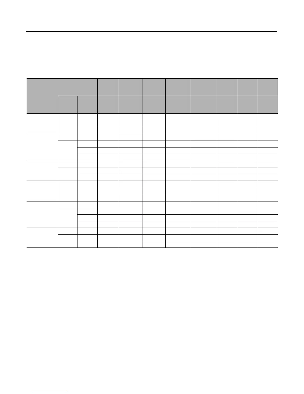
consult the MCC Modifications for Unit and Structure Compatibility Table,
Table 1.D, below.
Table 1.D MCC Modifications for Unit and Structure Compatibility
If Mounted in this
Type of
Section
(1)
,
(2)
Plug-In Units
No
Additional
Parts
Required
Requires
Style 1 Unit
Support Pan
Requires
Style 3 Unit
Support Pan
Requires
Style 3 Unit
Support Pan
w/ Bushing
Requires
Alternate Top
Horizontal
Wireway Pan
Requires
Door
Gasketing
Kit
Requires
Retrofit
Kit
(3)
Requires
Ground Bus
Kit
Space
Factor
Series — 2100H-UAJ1
2100H-UA12
100H-UJ1
2400H-USPA1
2400H-USPJ1
2100H-NA4A1
2100H-NA4J1
2100H-NA4A2
2100H-NA4J2
2100-GJ10 2400H-R1 2400H-GS1
NEMA Type 1 Series
A-D
(4)
1.0 or larger
A-E
(4)
9
——— — ———
F-L
(4)
—
9
——
9
(5)
———
M or later
(6)
—
9
——
9
(5)
——
9
NEMA Type 1 Series
E-J
(4)
0.5
(2)
N or later — — —
9
——
9 9
1.0 or larger
A-E
(4)
——
9
————
(8)
F-L
(4)
9
——— — ———
M or later
(6)
—— — — — ——
9
NEMA Type 1 Series
K or later
0.5
(2)
N or later
9
——— — ———
1.0 or larger
A-L
(4)
——
9
————
(8)
M or later
9
——— — ———
NEMA Type 1
w/gasket or Type 12
Series A-D
1.0 or larger
A-E
(4)
9
——— — ———
F-L
(4)
—
9
——
9
(5)
9
——
M or later —
9
——
9
(5)
9
—
9
NEMA Type 1
w/gasket or Type 12
Series E-J
(7)
0.5
(2)
N or later — — —
9
——
9 9
1.0 or larger
A-E
(4)
——
9
————
(8)
F-L
(4)
9
——— — ———
M or later — — — — — — —
9
NEMA Type 1
w/gasket or Type 12
Series K or later
0.5
(2)
N or later
9
——— — ———
1.0 or larger
A-L
(4)
——
9
————
(8)
M or later
9
——— — ———
(1)
When installing unit in topmost location in vertical sections, care must be taken to comply with the 2005 National Electrical Code (reference code: Article 404.8 and UL 845)
6’7” (2000 mm) unit handle-to-floor height limitation. A unit operating handle extender (2100-NE1) is available which provides 3” (76.2 mm) added height flexibility.
(2)
When Bulletin 2100, 0.5 space factor units are ordered unassembled or ordered for existing sections, a centralized wiring diagram holder kit (2100H-WDH) should be
ordered.
(3)
Permits installation of 0.5 space factor plug-in units in existing series E through J Bulletin 2100 vertical sections.
(4)
Replacement and renewal parts are no longer supported. Consult MCC Technical Support at 1-800-646-5800
(5)
Required only if series F or later, 1.0 space factor or larger Bulletin 2100 unit is installed in topmost location of series A through E vertical sections.
(6)
Consult MCC Technical Support at 1-800-646-5800 for assistance with possible door hinge requirements.
(7)
Series E-J sections cannot accommodate 0.5 space factor units in bottom-most unit location.
(8)
A ground strap can be used to ground units rather then installing a ground bus. See publication 2100-IN014x-EN-P.
 Loading...


