EasyManuals Logo

Allen-Bradley CENTERLINE User Manual

Allen-Bradley CENTERLINE
88 pages
To Next Page IconTo Next Page
To Previous Page IconTo Previous Page
Page #55 background imageLoading...
Page #55 background image
Publication 2100-IN012B-EN-P - April 2005
Installing and Removing Plug-In Units 5-7
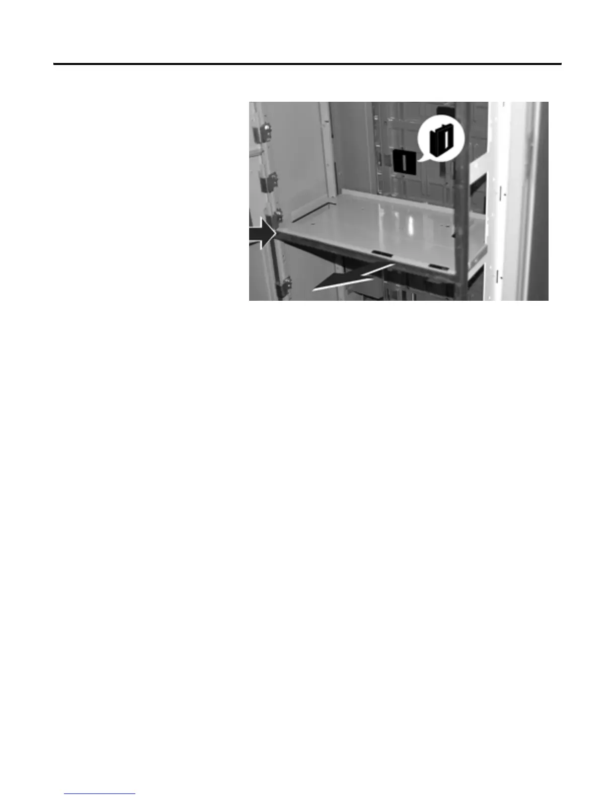
Figure 5-11 Install Protective Caps or Close Manual Shutters
3. Pull right side of support pan forward to release from left rear slot on
structure.
4. Push back on left side of support pan until support pan is free from
structure.
NOTE: Vertical sections may be supplied with plug-in stab opening
protective caps, manual shutters or automatic shutters. Refer to Step 5 if
any of these options are supplied.
5. Carefully install protective caps or close manual shutters after unit is
removed. Automatic shutters will close as units are removed.

Table of Contents

Questions and Answers:

Question and Answer IconNeed help?

Do you have a question about the Allen-Bradley CENTERLINE and is the answer not in the manual?

Allen-Bradley CENTERLINE Specifications

General IconGeneral
Short Circuit Current Rating (SCCR)Up to 100kA
Modular DesignYes
TypeMotor Control Center (MCC)
VoltageUp to 600V AC
Communication ProtocolsEtherNet/IP, DeviceNet
Enclosure TypeNEMA 1, NEMA 3R, NEMA 4, NEMA 4X, NEMA 12
Standards ComplianceUL 845, IEC 61439

Related product manuals