Publication 2100-IN012B-EN-P - April 2005
Installation Procedures 2-5
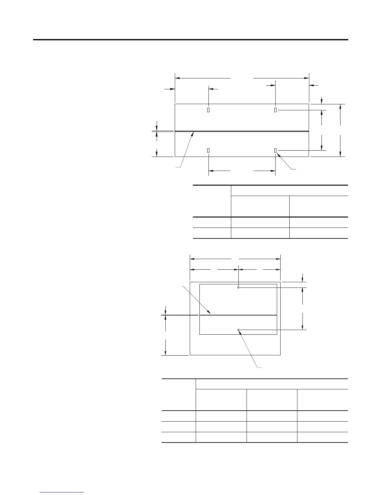
Figure 2.4 Mounting Dimensions for 15” and 20” Deep x 40” Wide Front-Mounted
Section
Figure 2.5 Mounting Dimensions for NEMA 3R and 4 Section
Section Depth
Dimension 15” (381mm) Deep 20” (508mm) Deep
in (mm) in (mm)
A 15 (381) 20 (508)
B 11.56 (294) 16.56 (421)
Interior Section Width
20” (508mm) Wide 25” (635mm) Wide 30” (762mm) Wide
in (mm) in (mm) in (mm)
A 25.00 (635) 30.00 (762) 35.00 (889)
B 13.75 (349) 16.25 (413) 18.75 (476)
C 11.25 (286) 13.75 (349) 16.25 (413)
.25" (6mm)
7.15" (102mm)
10.00" (254mm)
40.00"
(1016mm)
20.00"
(508mm)
10.00" (254mm)
1.69" (43mm)
A
B
(4) Mounting Slots
.56" x 1.13" Slots
14mm x 29mm Slots
Rear
Front
Standard
Ground Bus
2.87" (73mm)
14.06" (337mm)
16.56" (421mm)
A
BC
Ground Bus
.25" (6mm)
Front
Interior
Section
2 Mounting Holes
.63" (16mm) Diameter
Rear
 Loading...


