Rockwell Automation Publication 1756-RM012B-EN-P - April 2018 101
Studio 5000 Logix Designer Application, Version 31 or Later, Safety-application Instructions Appendix F
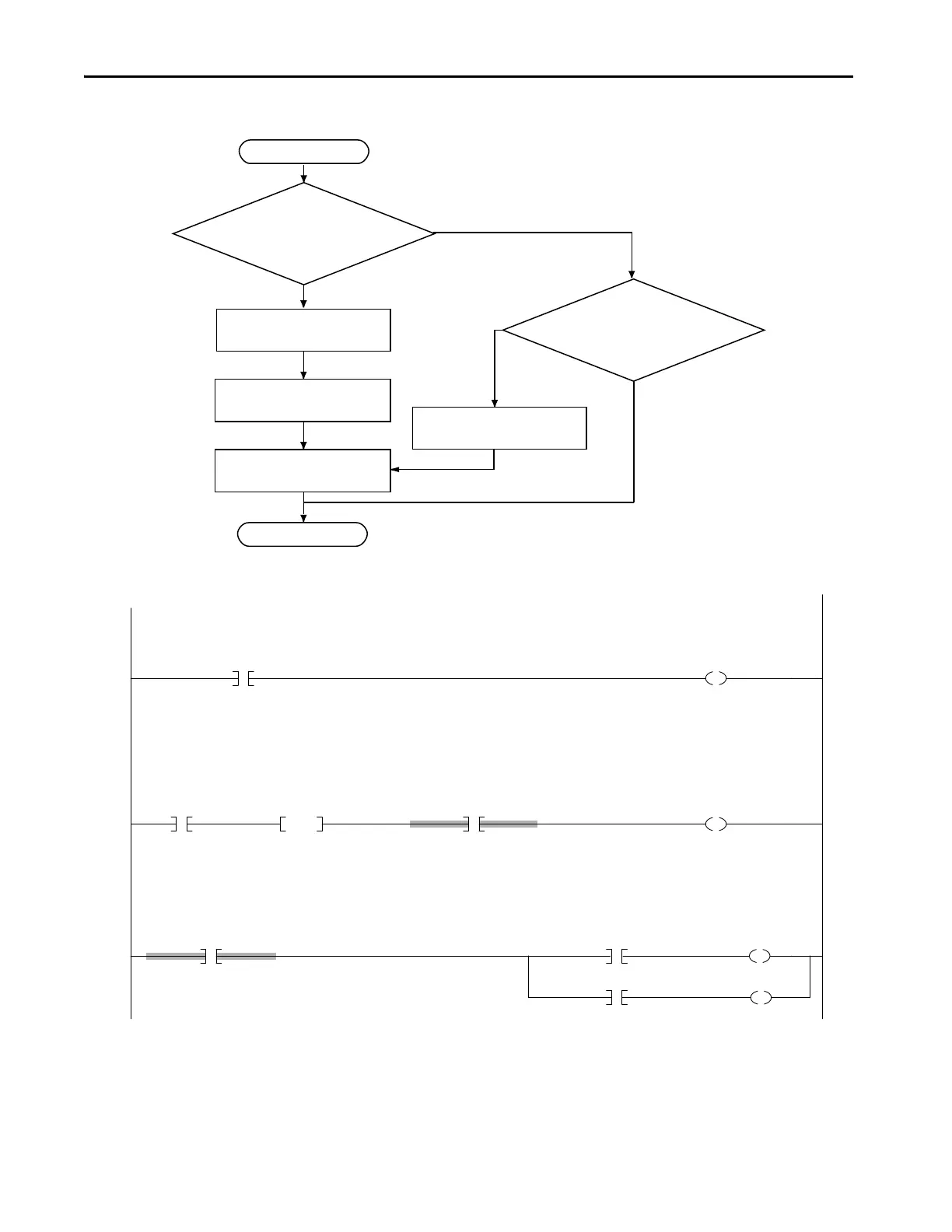
Figure 30 - Output Fault Latch and Reset Flowchart
Figure 31 - Ladder Diagram Example 3
Start
Does this safety function require operator
intervention after a safety output failure?
Write logic to latch output failure.
(Example Rung 0)
Is output fault information required for
diagnostic purposes?
No
Yes
Yes
No
Write logic to set outputs to a safe
state. (Example Rung 2)
Write logic to unlatch output failure
(Example Rung 1)
Write logic to latch output failure.
(Example Rung 0)
Done
0
/
/
Node30:I.OutputStatus
L
Node30OutputsFaulted
1
FaultReset
ONS
InputFaultResetOneShot
Node30:I.OutputStatus
U
Node30OutputsFaulted
2
Node30OutputsFaulted
RedundantOutputTag.O1
Node30:O.Pt00Data
Node30:O.Pt01Data
RedundantOutputTag.O2
Node 30 is an 8-point input/8-point output combination module.
If the output status is not OK, then latch the output faulted indication.
If the raising edge of the fault reset signal is detected and the input status is OK, then unlatch the inputs faulted indication.
 Loading...


