10 1769-L32E, 1769-L35E CompactLogix Controller
Publication
1769-IN020-C-EN-P - July 2007
Grounding Considerations on page 12 or DIN Rail Mounting on page
14.
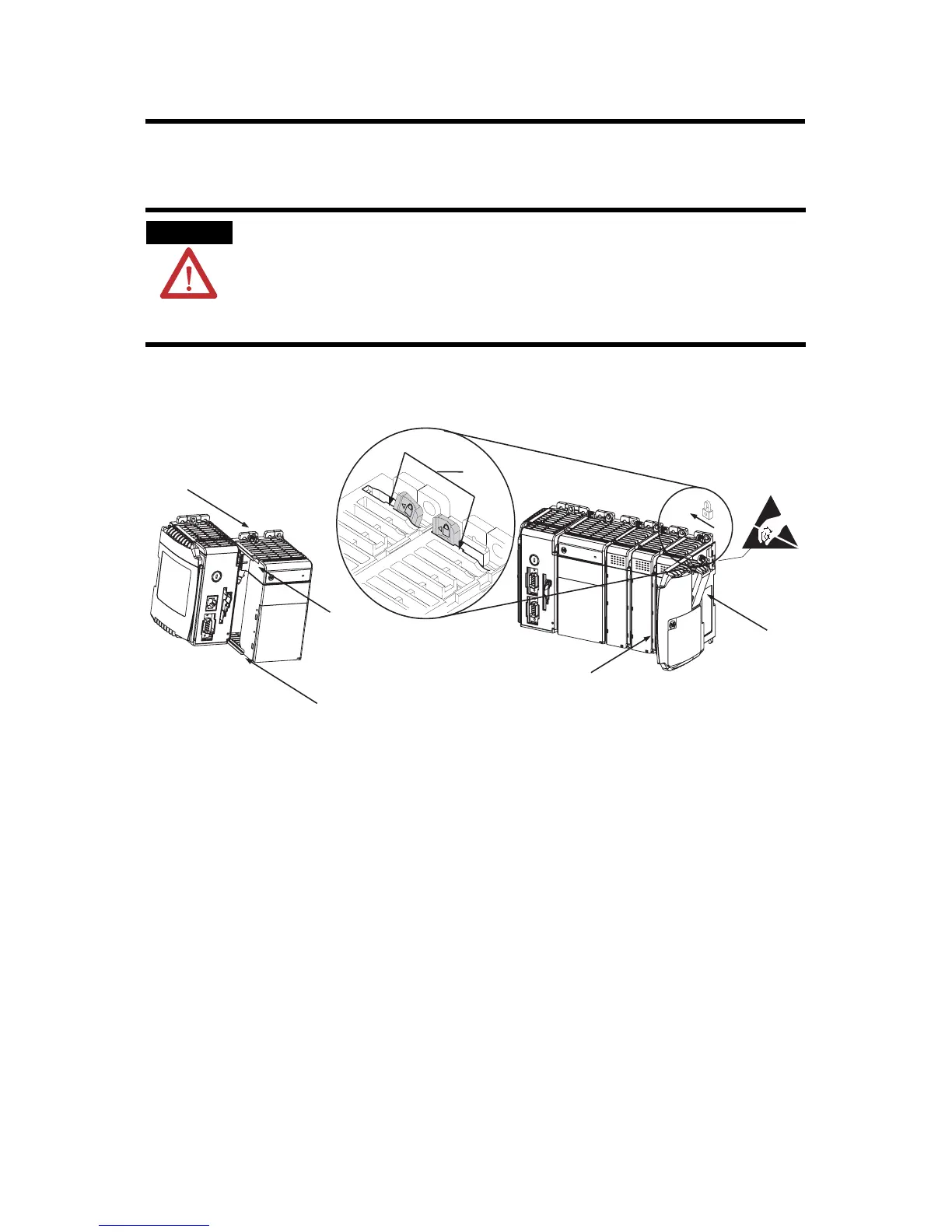
This procedure shows you how to install the controller in a
CompactLogix system.
1. Disconnect line power.
2. Check that the lever of the adjacent module (A) is in the
unlocked (fully right) position.
3. Use
the upper and lower tongue-and-groove slots (B) to
secure the modules together.
4. Mov
e the module back along the tongue-and-groove slots
until the bus connectors line up with each other.
5. Use your fingers or a small screwdriver to push the module’s
bus lever back slightly to clear the positioning tab (C).
WARNING
The CompactLogix controller is not designed for removal and insertion under power.
If you insert or remove the module while backplane power is on, an electrical arc can
occur. This could cause an explosion in hazardous location installations.
Be sure that power is removed or the area is nonhazardous before proceeding.
F
E
D
C
B
B
A

 Loading...


