4 Kinetix 5700 DC-bus Power Supplies
Rockwell Automation Publication 2198-IN009B-EN-P - June 2015
We recommend that you remove the grounding screw when the drive module is removed from
the panel and placed on its side on a solid surface equipped as a grounded static-safe workstation.
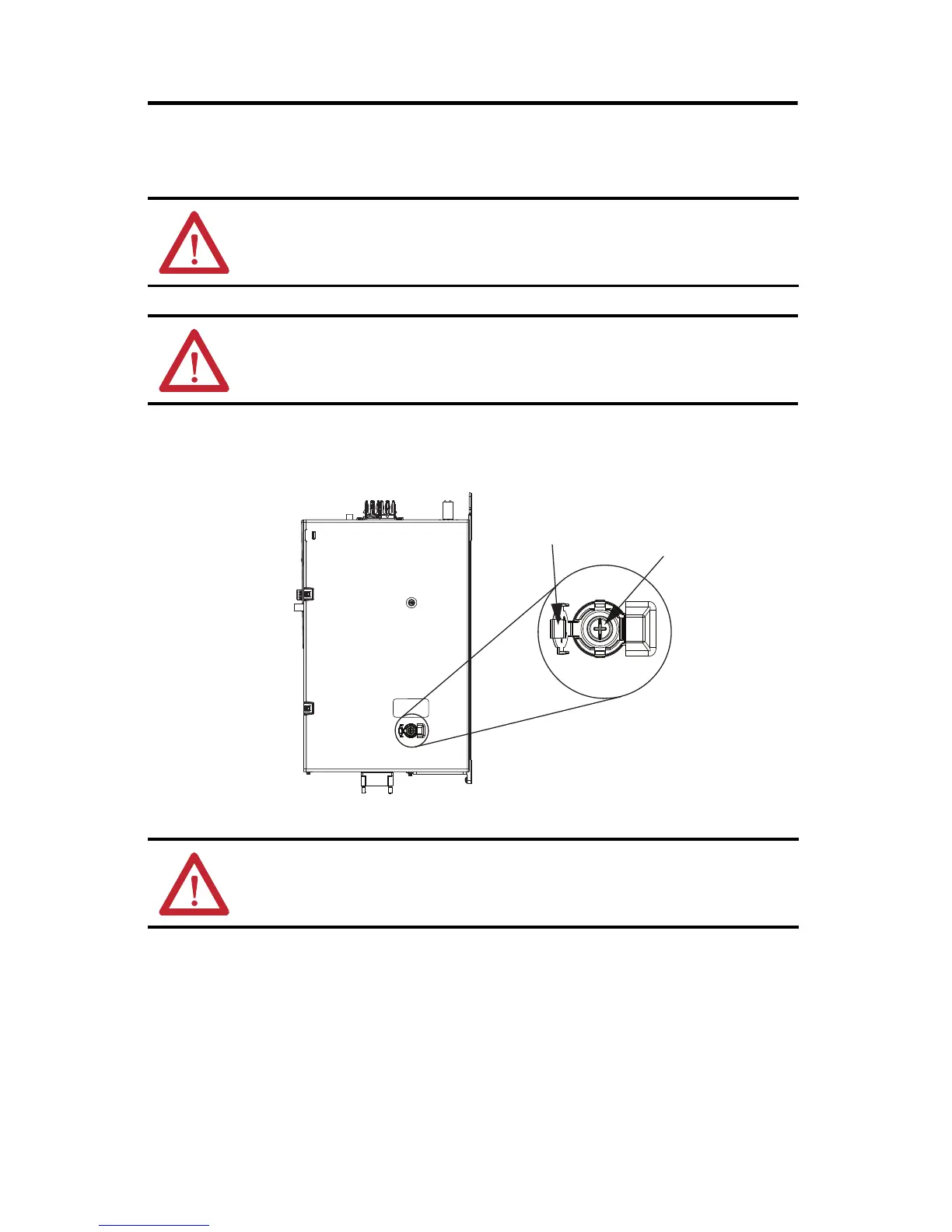
To access the grounding screw, open the small plastic door on the right side of the module.
Remove the Grounding Screw
ATTENTION: When you remove the grounding screw, the risk of equipment damage exists
because the unit no longer maintains line-to-neutral voltage protection.
ATTENTION: To avoid personal injury, the grounding-screw access door must be kept closed when
power is applied. If power was present, and then removed, wait at least 5 minutes for the DC-bus
voltage to dissipate, and verify that no DC-bus voltage exists before accessing the grounding screw.
ATTENTION: Risk of equipment damage exists. The drive-module ground configuration must be
accurately determined. Leave the grounding screw installed for grounded power configurations
(default). Remove the screw for ungrounded, corner-grounded, and impedance-grounded power.
Grounding screw installed
for grounded power configuration
(screw installed is default setting).
Remove screw for ungrounded, corner-grounded, and
impedance-grounded power configurations.
Grounding Screw
Access Door
DC-bus Power Supply
(side view)
Grounding Screw
 Loading...


