134 Rockwell Automation Publication 2198-UM002G-EN-P - February 2019
Chapter 5 Connect the Kinetix 5700 Drive System
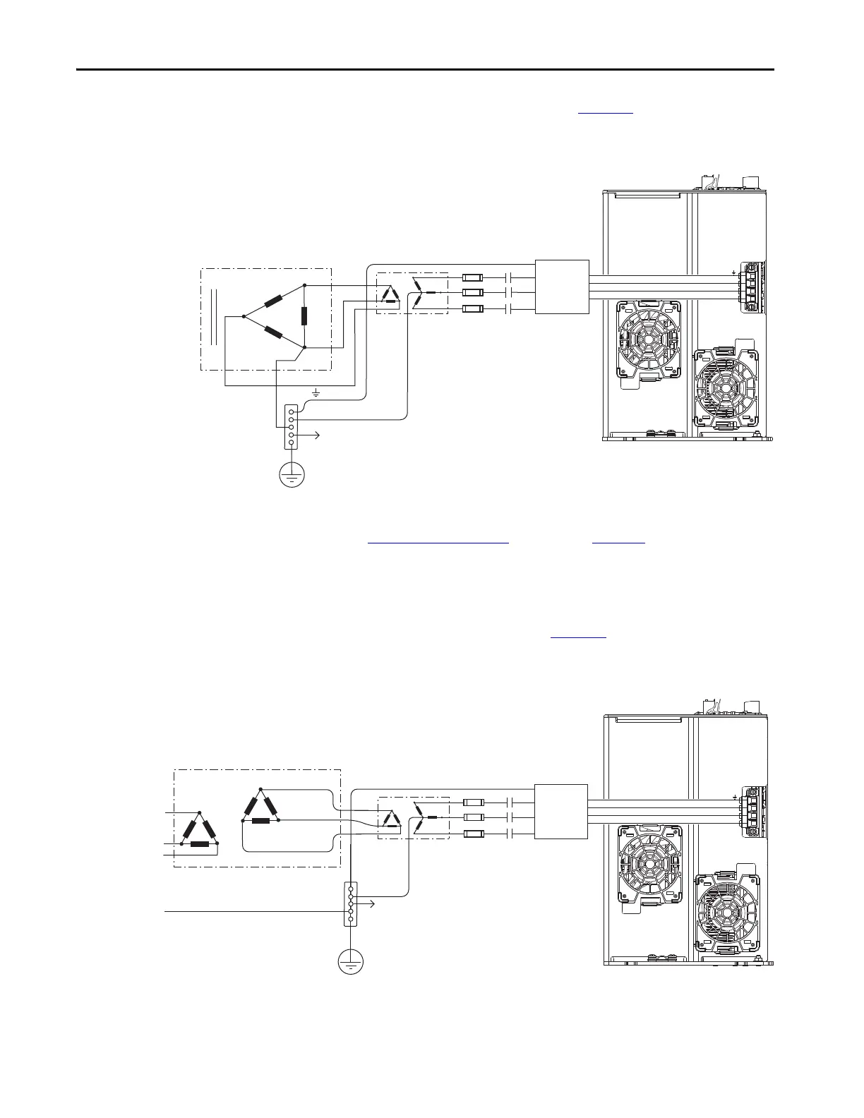
This corner-grounded power configuration (Figure 86) includes an isolation
transformer that results in grounded-wye power distribution.
Figure 86 - Corner-grounded Power Configuration (with isolation transformer)
(1) 2198-RPxxx power supply has the ground jumper installed. 2198-xxxx-ERSx inverters have the ground jumpers removed.
Refer to Power Wiring Examples beginning on page 343 for input power
interconnect diagrams.
Ungrounded Power Configurations
This ungrounded power configuration (Figure 87) includes an isolation
transformer that results in grounded-wye power distribution.
Figure 87 - Ungrounded Power Configuration (with isolation transformer)
(1) 2198-RPxxx power supply has the ground jumper installed. 2198-xxxx-ERSx inverters have the ground jumpers removed.
Transformer (Delta) Secondary
Bonded Cabinet
Ground
Transformer
Ground Grid or
Power Distribution Ground
Connect to drive module
ground stud.
Circuit
Protection
M1
Contactor
2198-RPxxx
(1)
Regenerative Bus Supply
(bottom view)
Isolation
Tran sf or me r
AC Line Filter
(required for CE)
Transformer
Three-phase
Input VAC
Chassis Ground
Bonded Cabinet
Ground
Ground Grid or
Power Distribution Ground
Connect to drive module
ground stud.
Circuit
Protection
M1
Contactor
2198-RPxxx
(1)
Regenerative Bus Supply
(bottom view)
Isolation
Tr an sf or me r
AC Line Filter
(required for CE)

 Loading...


