EasyManuals Logo

Allen-Bradley MicroLogix 1200 Installation Instructions

Allen-Bradley MicroLogix 1200
20 pages
To Next Page IconTo Next Page
To Previous Page IconTo Previous Page
Page #6 background imageLoading...
Page #6 background image
6 MicroLogix 1200 Analog Output Module
Publication 1762-IN016B-EN-P - December 2005
About the Analog Output Module
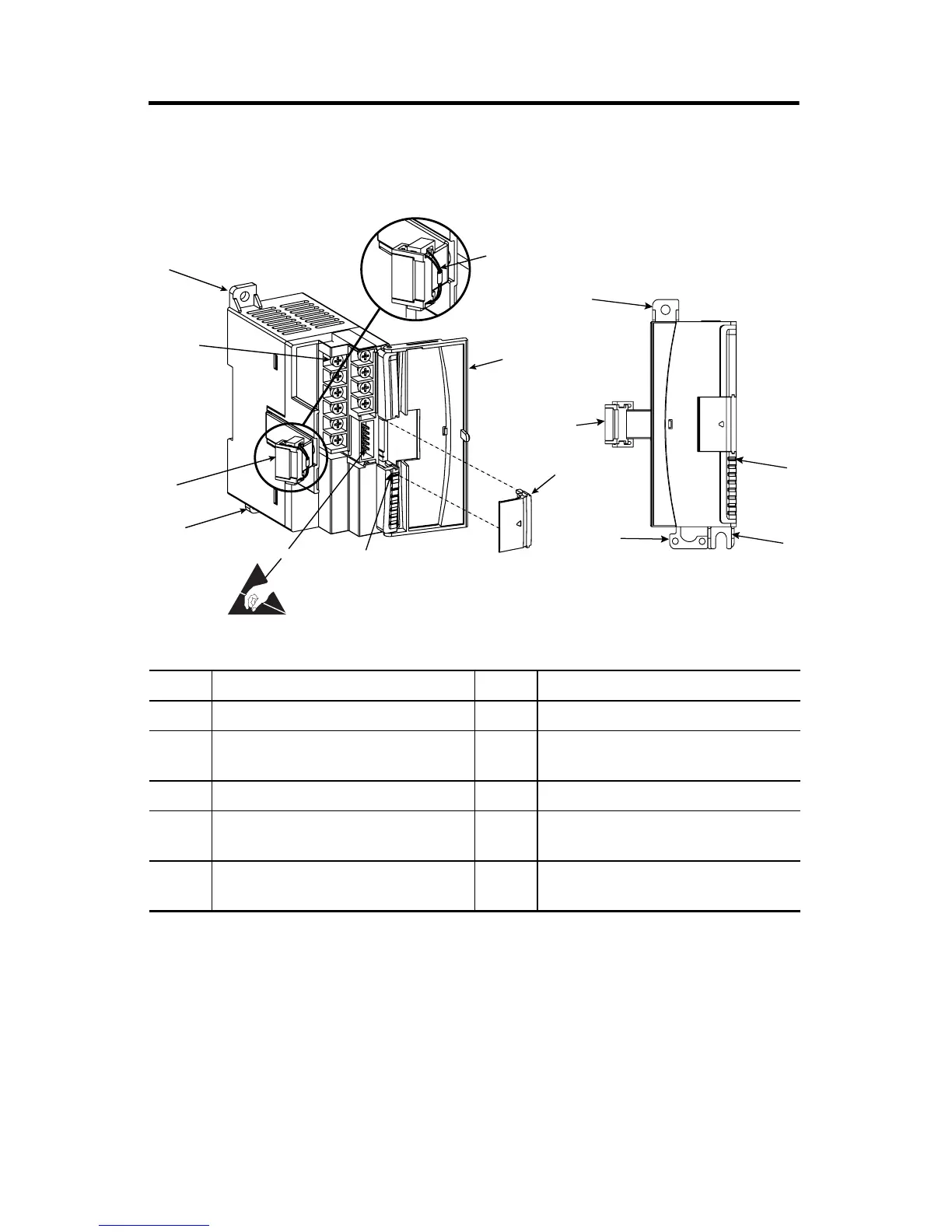
Figure 1 Product Description
Item Description Item Description
1a upper panel mounting tab 5 bus connector cover
1b lower panel mounting tab 6 flat ribbon cable with bus connector
(female)
2 power diagnostic LED 7 terminal block
3 module door with terminal identification
label
8 DIN rail latch
4 bus connector
with male pins
9 pull loop
1a
1b
5
2
3
9
4
6
7
1a
1b
2
6
8

Other manuals for Allen-Bradley MicroLogix 1200

Questions and Answers:

Question and Answer IconNeed help?

Do you have a question about the Allen-Bradley MicroLogix 1200 and is the answer not in the manual?

Allen-Bradley MicroLogix 1200 Specifications

General IconGeneral
SeriesMicroLogix 1200
TypeProgrammable Logic Controller (PLC)
MountingDIN rail or panel mount
Programming LanguageLadder Logic
Programming SoftwareRSLogix 500
I/O PointsUp to 40
Communication PortsRS-232, RS-485
Memory6 KB user memory
Power Supply24V DC or 120/240V AC
ExpansionSupports expansion I/O modules
Operating Temperature0°C to 55°C (32°F to 131°F)
Dimensions90 mm x 110 mm
Weight0.5 kg (1.1 lbs)

Related product manuals