14 MicroLogix 1200 Analog Output Module
Publication 1762-IN016B-EN-P - December 2005
Output Data File
For each module, slot x, words 0 through 3 contain the channel output data.
Words 0 through 3 contain the analog output data for channels 0 through 3,
respectively. The module ignores the “don’t care” bits (0 through 2), but checks the
sign bit (15). If bit 15 equals 1, the module sets the output value to 0V or 0 mA.
Words 0 through 3 contain the analog output data for channels 0 through 3,
respectively. The module ignores the “don’t care” bits (0 and 1), but checks the sign
bit (15), and bit 14. If bit 15 equals 1, the module sets the output value to 0V or
0 mA. If bit 15 equals zero and bit 14 equals 1, the module sets the output value to
10.5V dc or 21 mA.
Configuration Data File
The configuration of the format for analog outputs is made at going to run (GTR).
Changes made to the configuration file while in run mode have no effect on the
outputs.
The configuration table for analog outputs is shown in the Configuration Data FIle
table.
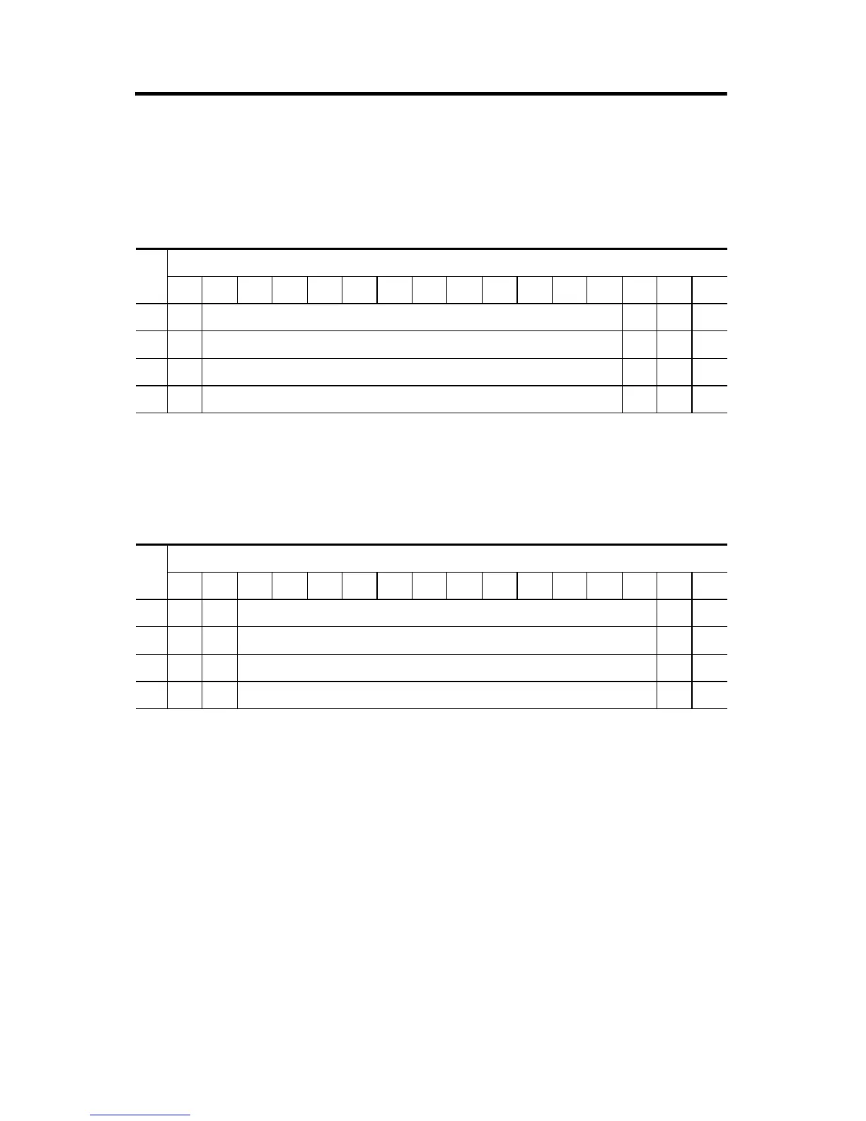
Raw/Proportional Format
Word
Bit Position
1514131211109876543210
0 0 Channel 0 Data 0 to 32,760 0 0 0
1 0 Channel 1 Data 0 to 32,760 0 0 0
2 0 Channel 2 Data 0 to 32,760 0 0 0
3 0 Channel 3 Data 0 to 32,760 0 0 0
Scaled-for-PID Format
Word
Bit Position
1514131211109876543210
0 0 0 Channel 0 Data 0 to 16,380 0 0
1 0 0 Channel 1 Data 0 to 16,380 0 0
2 0 0 Channel 2 Data 0 to 16,380 0 0
3 0 0 Channel 3 Data 0 to 16,380 0 0

 Loading...


