EasyManuals Logo

Allen-Bradley MicroLogix 1200 Installation Instructions

Allen-Bradley MicroLogix 1200
20 pages
To Next Page IconTo Next Page
To Previous Page IconTo Previous Page
Page #15 background imageLoading...
Page #15 background image
MicroLogix 1200 Analog Output Module 15
Publication 1762-IN016B-EN-P - December 2005
Bit 15 and Bits 7 through 0 - Reserved
These bits are reserved and are not checked by the module.
Data Format (Bits 14 through 12)
These bits indicate the format of the data as shown in the following table. Other
combinations of these bits are not supported and result in an error.
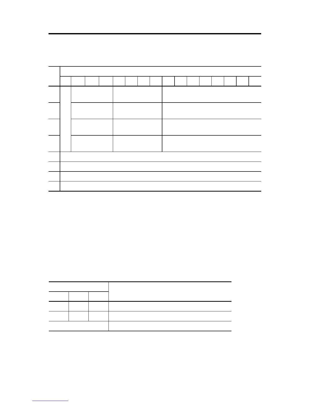
Configuration Data File
Word
Bit Position
1514131211109876543210
0
reserved
Data Format
Output Channel 0
Type/Range Select
Output Channel 0
reserved
1 Data Format
Output Channel 1
Type/Range Select
Output Channel 1
reserved
2 Data Format
Output Channel 2
Type/Range Select
Output Channel 2
reserved
3 Data Format
Output Channel 3
Type/Range Select
Output Channel 3
reserved
4reserved
5reserved
6reserved
7reserved
Bit Settings Data Format
14 13 12
0 0 0 Raw/Proportional
0 1 0 Scaled for PID
other Not Supported

Other manuals for Allen-Bradley MicroLogix 1200

Questions and Answers:

Question and Answer IconNeed help?

Do you have a question about the Allen-Bradley MicroLogix 1200 and is the answer not in the manual?

Allen-Bradley MicroLogix 1200 Specifications

General IconGeneral
SeriesMicroLogix 1200
TypeProgrammable Logic Controller (PLC)
MountingDIN rail or panel mount
Programming LanguageLadder Logic
Programming SoftwareRSLogix 500
I/O PointsUp to 40
Communication PortsRS-232, RS-485
Memory6 KB user memory
Power Supply24V DC or 120/240V AC
ExpansionSupports expansion I/O modules
Operating Temperature0°C to 55°C (32°F to 131°F)
Dimensions90 mm x 110 mm
Weight0.5 kg (1.1 lbs)

Related product manuals