116 Rockwell Automation Publication 520-UM001A-EN-E - February 2013
Chapter 3 Programming and Parameters
Advanced Program Group (continued)
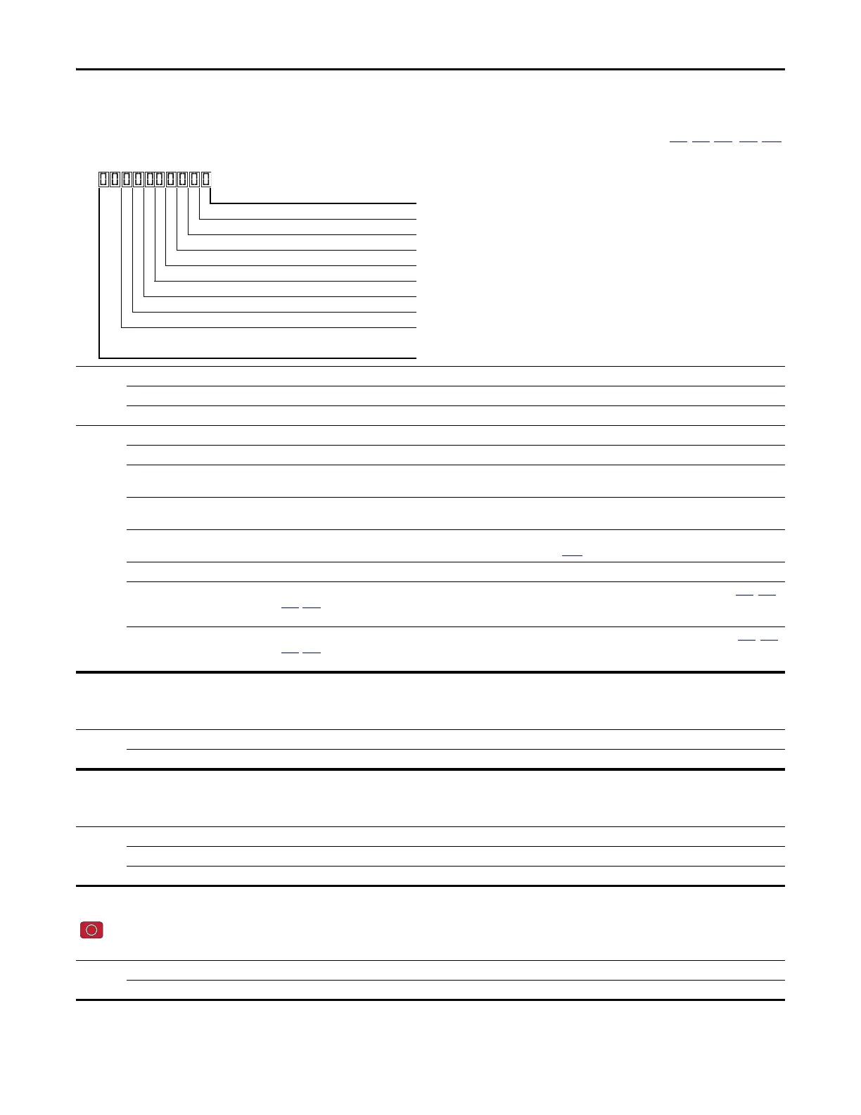
A560 [Enh Control Word] Related Parameter(s): t062, t063, t065 - t068, A571
Allows control of positioning and other functions through parameter control for use over comms. The functions replicate the digital input options and function in the same way.
Values Default: 0000 0000
Min/Max: 0000 0000/1111 1111
Display: 0000 0000
Digits 0 “Home Limit” In Positioning mode, this indicates the drive is at the home position
1 “Find Home” When set, the next start command causes the drive to find home. Set this bit to 0 after completing the homing routine.
2 “Hold Step” In Positioning mode, this input over-rides other inputs and causes the drive to remain at its current step (running at zero speed
once it reaches its position) until released.
3 “Pos Redefine” In Positioning mode, this input resets the home position to the current position of the machine. Set this bit to 0 after completing
the homing routine.
4 “Sync Enable” Must be used in order to hold the existing frequency when Sync Time is set to enable speed synchronization. When this bit is reset
to zero the drive accelerates to the new commanded frequency based on A571
[Sync Time] setting.
5 “Traverse Dis” When set the traverse function is disabled.
6 “Logic In 1” This provides an identical function as the “Logic In1” Digital Input option. This bit is logically ORed with a digital input t062
, t063,
t065-t068 [DigIn TermBlk xx] set to 24 “Logic In1”. It can be used to move through the Step-Logic functions (speed or position)
using comms control without requiring actual digital input transitions.
7 “Logic In 2” This provides and identical function as the “Logic In2” Digital Input option. This bit is logically ORed with a digital input t062
, t063,
t065-t068 [DigIn TermBlk xx] set to 25 “Logic In2”. It can be used to move through the Step-Logic functions (speed or position)
using comms control without requiring actual digital input transitions.
1 = Input Present, 0 = Input Not Present
Home Limit Digit 1
Find Home Digit 2
Hold Step Digit 3
Pos Redefine Digit 4
Sync Enable Digit 5
Traverse Dis Digit 6
Logic In 1 Digit 7
Logic In 2 Digit 8
Not Used
A561 [Home Save]
Determines whether the current position is saved on power down.
Options 0 “Home Reset” (Default) Position resets to zero on power up.
1“Home Saved”
A562 [Find Home Freq]
Sets the maximum frequency the drive uses when “Find Home” is issued.
Values Default: 10.0 Hz
Min/Max: 0.1/500.0 Hz
Display: 0.1 Hz
A563 [Find Home Dir]
Stop drive before changing this parameter.
Sets the direction the drive commands when “Find Home” is issued.
Options 0“Forward” (Default)
1“Reverse”
 Loading...


