Rockwell Automation Publication 520-UM001A-EN-E - February 2013 37
Installation/Wiring Chapter 1
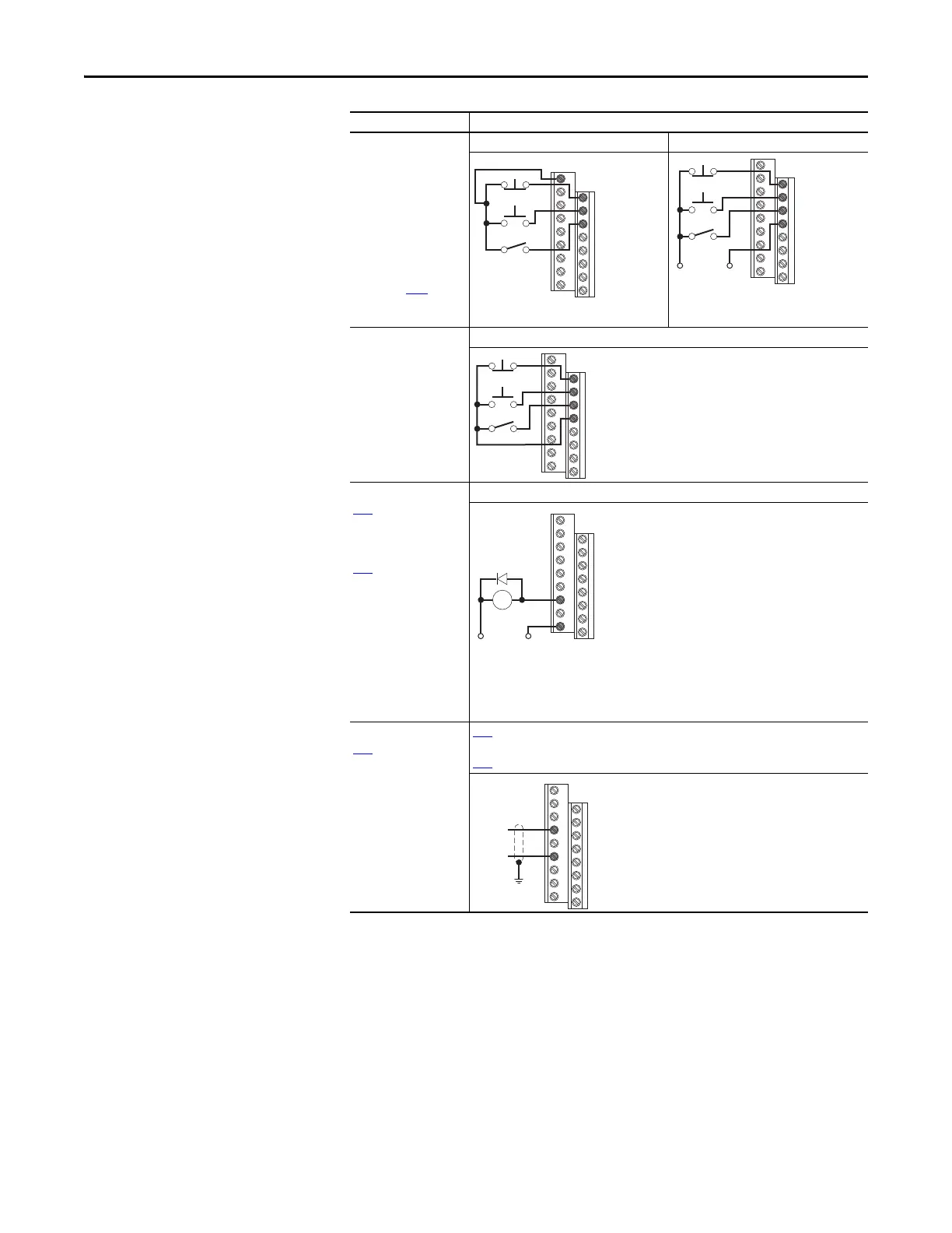
3 Wire SRC Control -
Reversing
P046 [Start Source 1] = 2,
t062 [DigIn TermBlk 02]
= 49 and t063 [DigIn
TermBlk 03] = 51
A momentary input will
start the drive. A stop
input to I/O Terminal 01
will stop the drive as
specified by P045 [Stop
Mode]. I/O Terminal 03
determines direction.
Internal Supply (SRC) External Supply (SRC)
Each digital input draws 6 mA.
3 Wire SNK Control -
Reversing
Internal Supply (SNK)
Opto Output (1 & 2)
t069
[Opto Out1 Sel]
determines Opto-Output 1
(I/O Terminal 17)
operation.
t072 [Opto Out2 Sel]
determines Opto-Output 2
(I/O Terminal 18)
operation.
When using Opto-Output
with an inductive load
such as a relay, install a
recovery diode parallel to
the relay as shown, to
prevent damage to the
output.
Opto-Output 1
Each Opto-Output is rated 30V DC 50 mA (Non-inductive).
Analog Output
t088
[Analog Out Sel]
determines analog output
type and drive conditions.
0-10V,
1k Ω minimum
0-20 mA/4-20 mA,
525 Ω maximum
t088
[Analog Out Sel] = 0 through 23
The Analog Output Select jumper must be set to match the analog output signal mode set in
t088
[Analog Out Sel].
I/O Connection Example
11
01
02
03
Stop
Start
Direction
+24V Common
Stop
Start
Direction
01
02
03
04
Stop
Start
Direction
01
02
03
04
Common+24V
CR
19
17

 Loading...


