36 Rockwell Automation Publication 520-UM001A-EN-E - February 2013
Chapter 1 Installation/Wiring
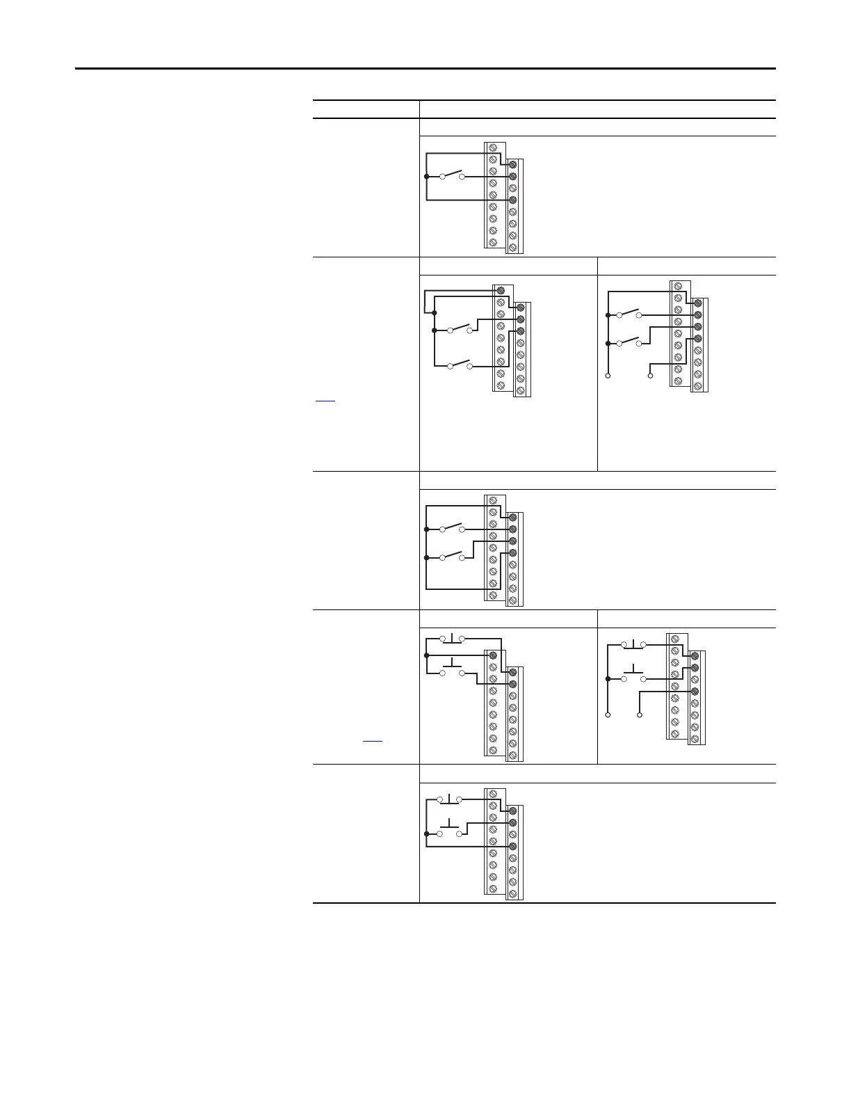
2 Wire SNK Control -
Non-Reversing
Internal Supply (SNK)
2 Wire SRC Control -
Run FWD/Run REV
P046 [Start Source 1] = 2,
t062 [DigIn TermBlk 02]
= 48 and t063 [DigIn
TermBlk 03] = 50
Input must be active for
the drive to run. When
input is opened, the drive
will stop as specified by
P045
[Stop Mode].
If both Run Forward and
Run Reverse inputs are
closed at the same time,
an undetermined state
could occur.
Internal Supply (SRC) External Supply (SRC)
Each digital input draws 6 mA.
2 Wire SNK Control -
Run FWD/Run REV
Internal Supply (SNK)
3 Wire SRC Control -
Non-Reversing
P046 [Start Source 1] = 2
and t062 [DigIn TermBlk
02] = 49
A momentary input will
start the drive. A stop
input to I/O Terminal 01
will stop the drive as
specified by P045
[Stop
Mode].
Internal Supply (SRC) External Supply (SRC)
Each digital input draws 6 mA.
3 Wire SNK Control -
Non-Reversing
Internal Supply (SNK)
I/O Connection Example
Stop-Run
01
02
03
04
11
01
02
03
Stop-Run
Forward
Stop-Run
Reverse
Common
01
02
03
04
Stop-Run
Forward
Stop-Run
Reverse
+24V
Stop-Run
Forward
Stop-Run
Reverse
01
02
03
04
11
01
02
Stop
Start
01
02
04
+24V
Common
Stop
Start
Stop
Start
01
02
04
 Loading...


