Rockwell Automation Publication 520-UM001A-EN-E - February 2013 35
Installation/Wiring Chapter 1
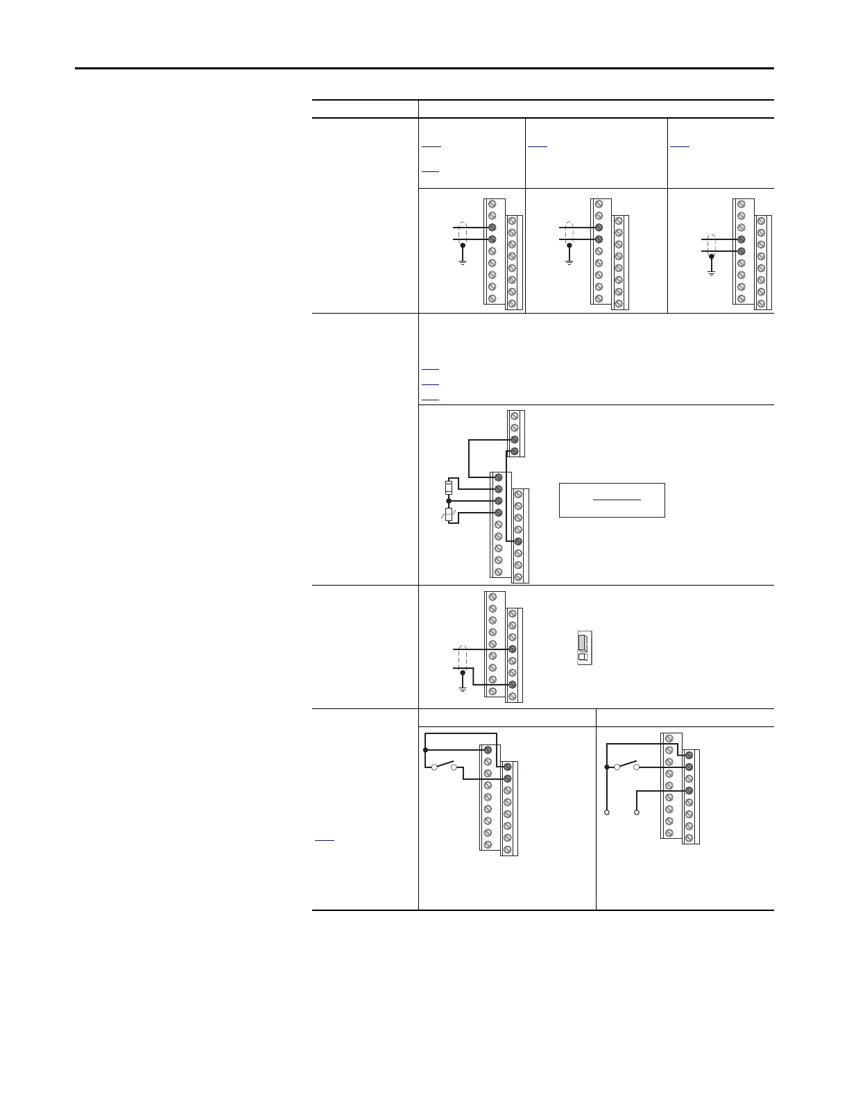
Analog Input
0-10V, 100k Ω impedance
4-20 mA, 250 Ω
impedance
Bipolar
P047 [Speed Reference1]
= 5 “0-10V Input” and
t093 [10V Bipolar Enbl]
= 1 “Bi-Polar In”
Unipolar (Voltage)
P047 [Speed Reference1]
= 5 “0-10V Input”
Unipolar (Current)
P047 [Speed Reference1]
= 6 “4-20mA Input”
Analog Input, PTC
For Drive Fault
Wire the PTC and External Resistor (typically matched to the PTC Hot Resistance) to I/O
Terminals 12, 13, 14.
Wire R2/R3 Relay Output (SRC) to I/O Terminals 5 & 11.
t065
[DigIn TermBlk 05] = 12 “Aux Fault”
t081
[Relay Out 2 Sel] = 10 “Above Anlg V”
t082 [Relay Out 2 Level] = % Voltage Trip
Pulse Train Input
t067 [DigIn TermBlk 07]
= 52
Use P047, P049 and P051
[Speed Referencex] to
select pulse input. Jumper
for DigIn TermBlk 07 Sel
must be moved to Pulse
In.
2 Wire SRC Control -
Non-Reversing
P046 [Start Source 1] = 2
and t062 [DigIn TermBlk
02] = 48
Input must be active for
the drive to run. When
input is opened, the drive
will stop as specified by
P045
[Stop Mode].
If desired, a User Supplied
24V DC power source can
be used. Refer to the
“External Supply (SRC)”
example.
Internal Supply (SRC) External Supply (SRC)
Each digital input draws 6 mA.
I/O Connection Example
13
14
±10V
Common
11
12
13
14
R5
R6
05
%V
Trip
= X 100
R
PTC (hot)
R
PTC (hot)
+ R
e
R
e
R
PTC
Common
Pulse In
07
04
DigIn TermBlk 07 Sel
Pulse In
Digital
Input
11
01
02
Stop-Run
+24V Common
01
02
04
Stop-Run
 Loading...


