34 Rockwell Automation Publication 520-UM001A-EN-E - February 2013
Chapter 1 Installation/Wiring
I/O Wiring Examples
13 ±10V In Not Active For external 0-10V (unipolar) or ±10V (bipolar) input supply or
potentiometer wiper.
Input impedance:
Voltage source = 100 kΩ
Allowable potentiometer resistance range = 1...10 kΩ
P047, P049,
t062, t063,
t065, t066,
t093, A459,
A471
14 Analog Common – Return for the analog I/O. Electrically isolated (along with the
analog I/O) from the rest of the drive.
–
15 4-20mA In Not Active For external 4-20 mA input supply.
Input impedance = 250 Ω
P047, P049,
t062, t063,
t065, t066,
A459, A471
16 Analog Output OutFreq 0-10 The default analog output is 0-10V. To convert a current value,
change the Analog Output jumper to 0-20 mA. Program with
t088 [Analog Out Sel]. Maximum analog value can be scaled
with t089 [Analog Out High].
Maximum Load: 4-20 mA = 525 Ω (10.5V)
0-10V = 1 kΩ (10 mA)
t088, t089
17 Opto Output 1 Motor Running Program with t069 [Opto Out1 Sel].
Each Opto-Output is rated 30V DC 50 mA (Non-inductive).
t069, t070,
t075
18 Opto Output 2 At Frequency Program with t072 [Opto Out1 Sel].
Each Opto-Output is rated 30V DC 50 mA (Non-inductive).
t072, t073,
t075
19 Opto Common – The emitters of the Optocoupler Outputs (1 and 2) are tied
together at Optocoupler Common. Electrically isolated from the
rest of the drive.
–
(1) See Footnote (1) on page 32.
Control I/O Terminal Block Wire Specifications
Frame Maximum Wire Size
(1)
(1) Maximum/minimum sizes that the terminal block will accept – these are not recommendations.
Minimum Wire Size
(1)
Torque
A...E 1.3 mm
2
(16 AWG) 0.13 mm
2
(26 AWG) 0.71...0.86 Nm (6.2...7.6 lb-in.)
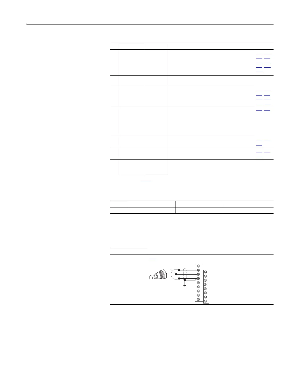
I/O Connection Example
Potentiometer
1...10k Ω Pot.
Recommended
(2 W minimum)
P047
[Speed Reference1] = 5 “0-10V Input”
Control I/O Terminal Designations
No. Signal Default Description Parameter
12
13
14
 Loading...


