Rockwell Automation Publication 520-UM001A-EN-E - February 2013 33
Installation/Wiring Chapter 1
(2) Two wire control shown. For three wire control use a momentary input on I/O Terminal 02 to command a start. Use a
maintained input for I/O Terminal 03 to change direction.
(3) When using an opto output with an inductive load such as a relay, install a recovery diode parallel to the relay as shown, to prevent
damage to the output.
t064 [2-Wire Mode] Normal Stop I/O Terminal 01 Stop
0 “Edge Trigger” Per P045
[Stop Mode]
Coast
1 “Level Sense” Per P045 [Stop Mode]
2 “Hi-Spd Edge” Coast
3 “Momentary” Per P045 [Stop Mode]
The drive is shipped with a jumper installed between I/O Terminals 01 and 11.
Remove this jumper when using I/O Terminal 01 as a stop or enable input.
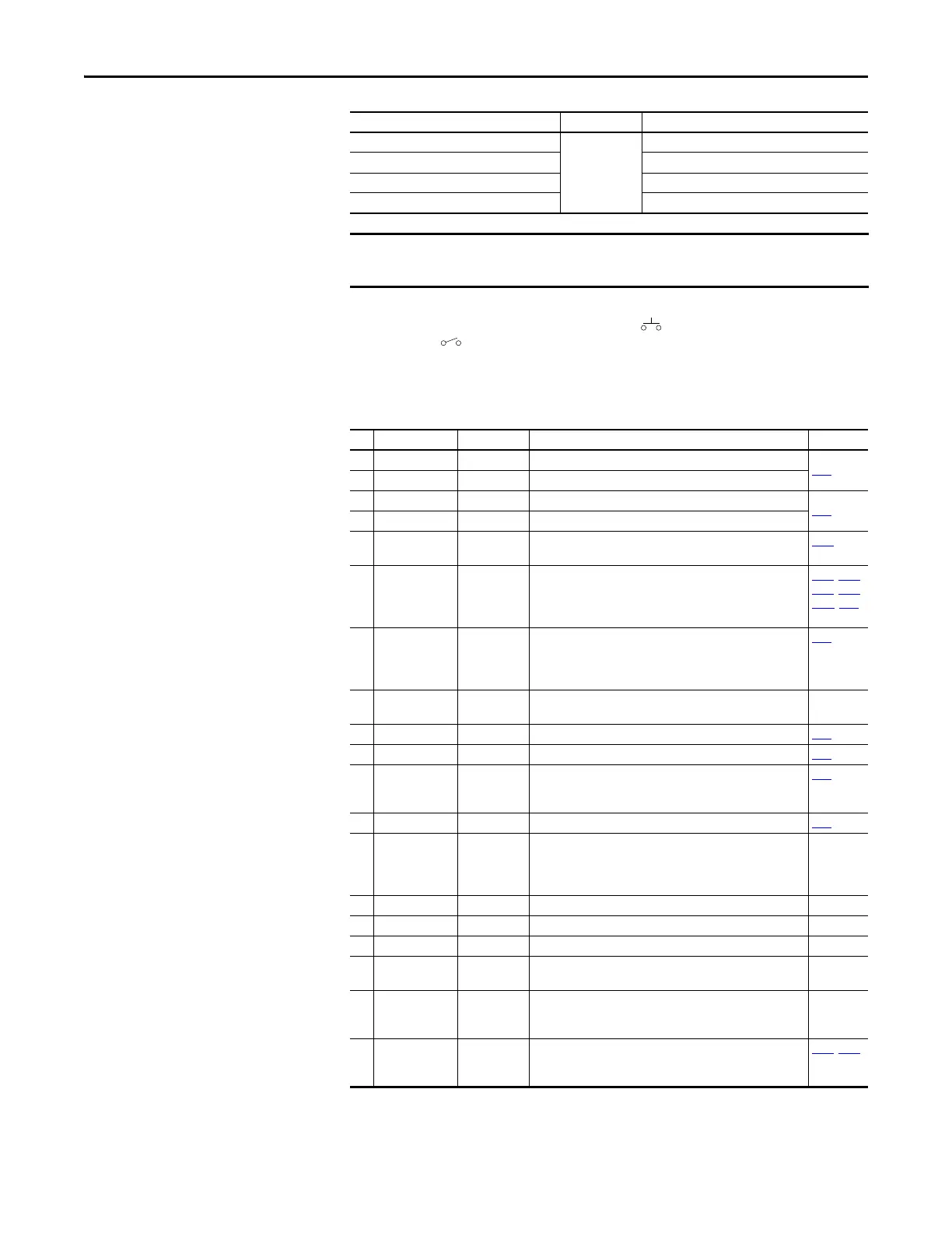
Control I/O Terminal Designations
No. Signal Default Description Parameter
R1 Relay 1 N.O. Fault Normally open contact for output relay.
t076
R2 Relay 1 Common Fault Common for output relay.
R5 Relay 2 Common Motor Running Common for output relay.
t081
R6 Relay 2 N.C. Motor Running Normally closed contact for output relay.
01 Stop Coast Three wire stop. However, it functions as a stop under all input
modes and cannot be disabled.
P045
(1)
02 DigIn TermBlk 02/
Start/Run FWD
Run FWD Used to initiate motion and also can be used as a programmable
digital input. It can be programmed with t062 [DigIn TermBlk
02] as three wire (Start/Dir with Stop) or two wire (Run FWD/
Run REV) control.
P045, P046,
P048, P050,
A544, t062
03 DigIn TermBlk 03/
Dir/Run REV
Run REV Used to initiate motion and also can be used as a programmable
digital input. It can be programmed with t063 [DigIn TermBlk
03] as three wire (Start/Dir with Stop) or two wire (Run FWD/
Run REV) control.
t063
04 Digital Common – Return for digital I/O. Electrically isolated (along with the digital
I/O) from the rest of the drive.
–
05 DigIn TermBlk 05 Preset Freq Program with t065 [DigIn TermBlk 05]. t065
06 DigIn TermBlk 06 Preset Freq Program with t066 [DigIn TermBlk 06]. t066
07 DigIn TermBlk 07/
Pulse In
Start Source 2
+ Speed
Reference2
Program with t067 [DigIn TermBlk 07]. Also functions as a Pulse
Train input for reference or speed feedback. The maximum
frequency is 100 kHz.
t067
08 DigIn TermBlk 08 Jog Forward Program with t068 [DigIn TermBlk 08]. t068
C1 C1 – This terminal is tied directly to the RJ-45 and USB shields on the
Keypad printed circuit board (PCB). Ties this shield to earth
ground in order to improve noise immunity when using external
communication peripherals.
–
C2 C2 – This is the signal common for the communication signals. –
S1 Safety 1 – Safety input 1. Current consumption is 6 mA. –
S2 Safety 2 – Safety input 2. Current consumption is 6 mA. –
S+ Safety +24V – +24V supply for safety circuit. Internally tied to the +24V DC
source (Pin 11).
–
11 +24V DC – Referenced to Digital Common.
Drive supplied power for digital inputs.
Maximum output current is 100 mA.
–
12 +10V DC – Referenced to Analog Common.
Drive supplied power for 0...10V external potentiometer.
Maximum output current is 15 mA.
P047
, P049

 Loading...


