Programming and Parameters 3-27
SPEED COMMAND
Process PI
Important: Parameters in the Process PI Group are used to enable and tune the
PI Loop. In order to allow the PI Loop to control drive operation, program the
following:
Standard Control Option – Parameter 080 [Speed Mode] must be set to 2
“Process PI” and parameter 125, bit 0 must be set to “1, Enabled.”.
Vector Control Option – Only requires setting parameter 125, bit 0 to “1, Enabled.”
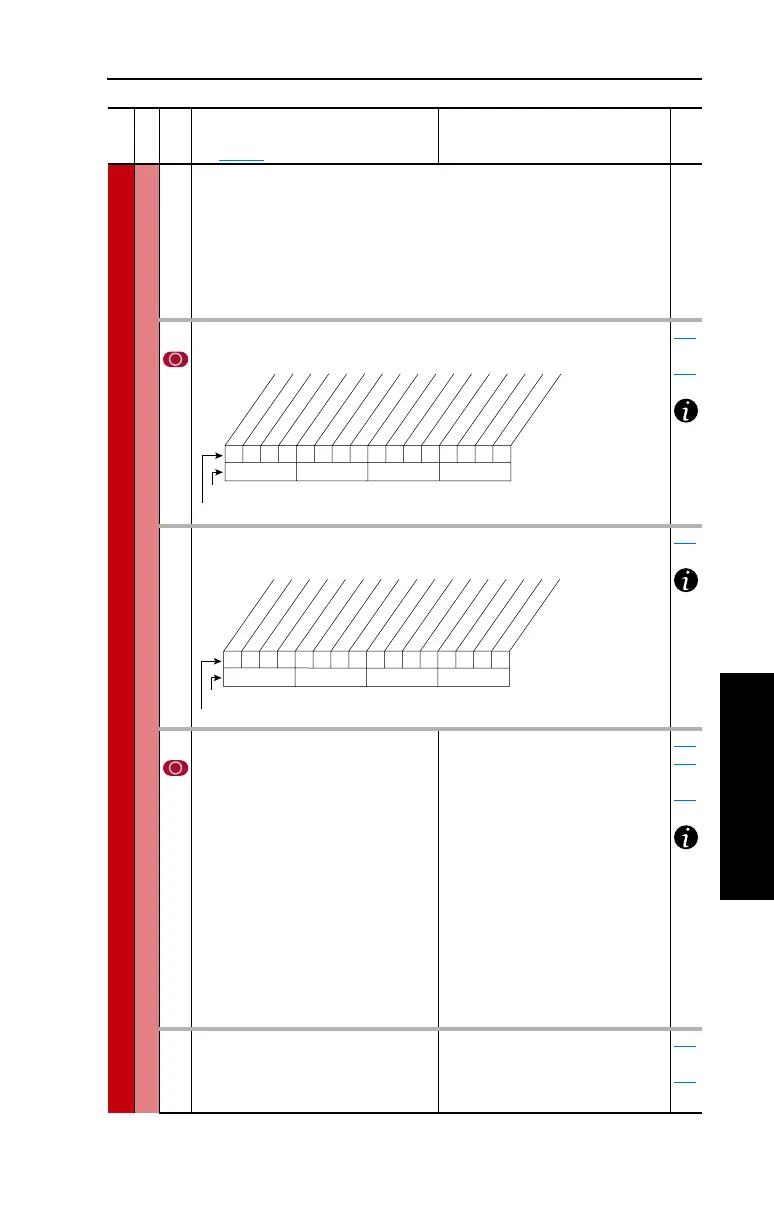
124 [PI Configuration]
Sets configuration of the PI regulator.
124
thru
138
125 [PI Control]
Controls the PI regulator.
080
126 [PI Reference Sel]
Selects the source of the PI reference.
(1)
Vector firmware 3.001 and later.
Default:
Options:
0
0
1
2
3-6
7
8
9
10
11-17
18-22
23-24
25
26
27
28
“PI Setpoint”
“PI Setpoint”
“Analog In 1”
“Analog In 2”
“Reserved”
“Pulse In”
“Encoder”
“MOP Level”
“Master Ref”
“Preset Spd1-7”
“DPI Port 1-5”
“Reserved”
“Scale Block 1”
(1)
“Scale Block 2”
(1)
“Scale Block 3”
(1)
“Scale Block 4”
(1)
024
124
thru
138
127 [PI Setpoint]
Provides an internal fixed value for
process setpoint when [PI Reference Sel]
is set to “PI Setpoint.”
Default:
Min/Max:
Units:
50.00%
–/+100.00% of Maximum
Process Value
0.01%
124
thru
138
File
Group
No.
Parameter Name & Description
See page 3-2 for symbol descriptions
Values
Related
0000000000xxxxxx
10 01234567891112131415
1 =Enabled
0 =Disabled
x =Reserved
Bit # * Vector Control Option Only
** Vector firmware 3.001 & later
Factory Default Bit Values
Excl Mode
Invert Error
Preload Mode
Ramp Ref
Zero Clamp
Feedbak Sqrt
Stop Mode
Anti-Wind Up
Torque Trim *
% of Ref **
00x 0xxxxxxxxxxxx
10 01234567891112131415
1 =Enabled
0 =Disabled
x =Reserved
Bit #
Factory Default Bit Values
PI Enable
PI Hold
PI Reset
 Loading...


