3-22 Programming and Parameters
SPEED COMMAND
Spd Mode & Limits
080 [Speed Mode]
Sets the method of speed regulation.
Default:
Options:
0
0
1
2
“Open Loop”
“Open Loop”
“Slip Comp”
“Process PI”
412
152
[Feedback Select]
Selects the source for motor speed
feedback. Note that all selections are
available when using Process PI.
“Open Loop” (0) - no encoder is present,
and slip compensation is not needed.
“Slip Comp” (1) - tight speed control is
needed, and encoder is not present.
“Encoder” (3) - an encoder is present.
“Simulator” (5) - Simulates a motor for
testing drive operation & interface check.
Default:
Options:
0
0
1
2
3
4
5
“Open Loop”
“Open Loop”
“Slip Comp”
“Reserved”
“Encoder”
“Reserved”
“Simulator”
081 [Minimum Speed]
Sets the low limit for speed reference
after scaling is applied. Refer to
parameter 083 [Overspeed Limit].
Default:
Min/Max:
Units:
0.0
0.0/[Maximum Speed]
0.1 Hz
0.1 RPM
079
083
092
095
082 [Maximum Speed]
Sets the high limit for speed reference
after scaling is applied. Refer to
parameter 083 [Overspeed Limit].
Default:
Min/Max:
Units:
50.0 or 60.0 Hz (volt class)
[Motor NP RPM]
5.0/400.0 Hz
75.0/24000.0 RPM
0.1 Hz
0.1 RPM
055
079
083
091
094
202
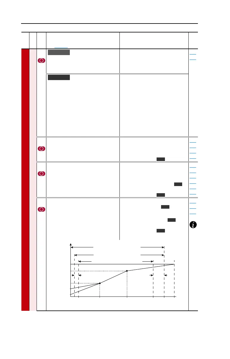
083 [Overspeed Limit]
Sets the incremental amount of the
output frequency (above [Maximum
Speed]) allowable for functions such as
slip compensation.
[Maximum Speed] + [Overspeed Limit]
must be ≤ [Maximum Freq]
Default:
Min/Max:
Units:
10.0 Hz
300.0 RPM
0.0/20.0 Hz
0.0/600.0 RPM
0.1 Hz
0.1 RPM
055
079
082
File
Group
No.
Parameter Name & Description
See page 3-2 for symbol descriptions
Values
Related
Standard
Vector
Vector
Vector
Vector
Vector
Vector
Vector
Allowable Output Frequency Range
Bus Regulation or Current Limit
Voltage
Frequency
Allowable Output Frequency Range
Normal Operation
Allowable Reference Frequency Range
Frequency Trim due to
Speed Control Mode
Max Volts
Motor Volts
Break Volts
Start Boost
Run
0 Min
Speed
Motor
Hz
Max
Speed
Output
Freq Limit
Max
Freq
Break
Frequency
Overspeed
Limit
 Loading...


