3-36 Programming and Parameters
DYNAMIC CONTROL
Restart Modes
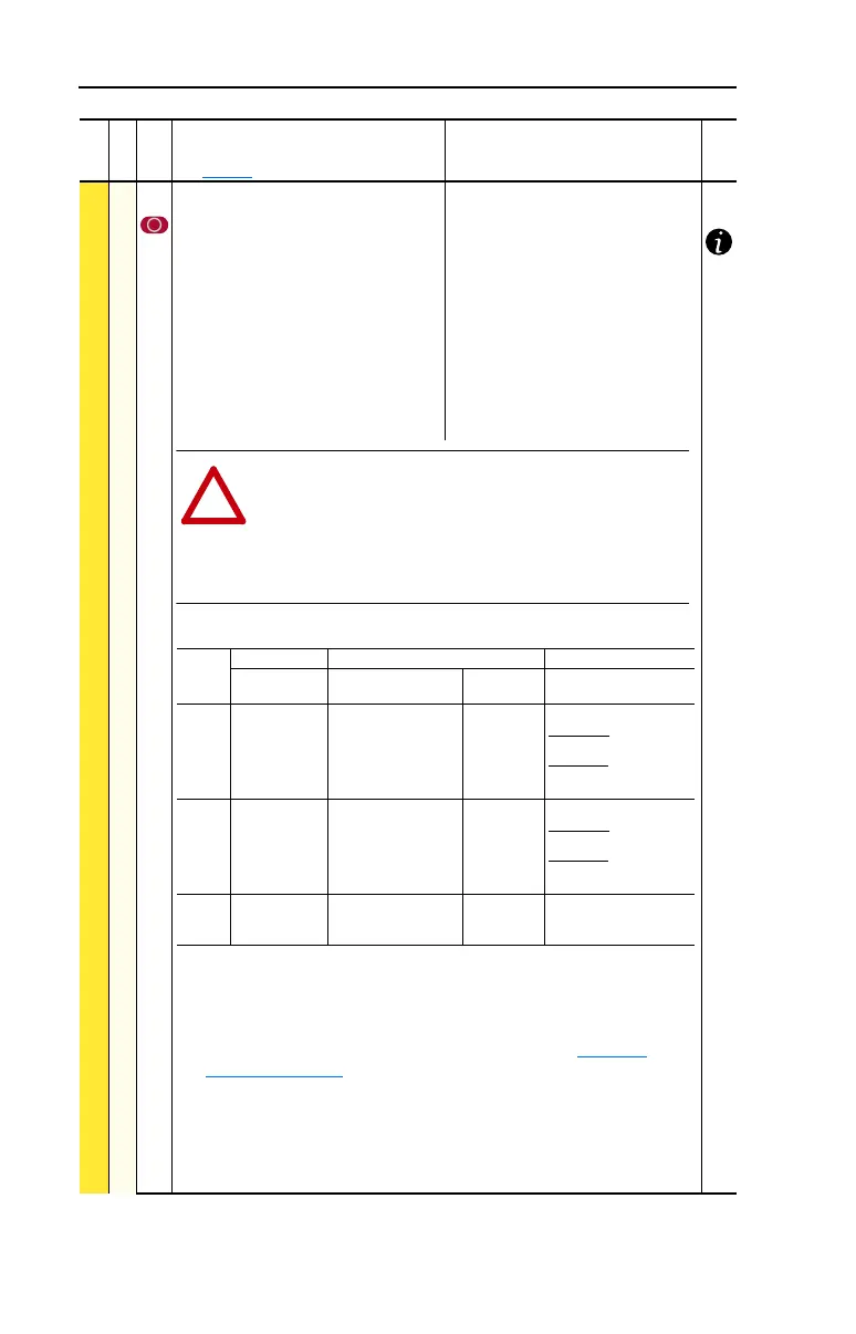
178 [Sleep-Wake Mode]
Enables/disables the Sleep/Wake
function. Important: When enabled, the
following conditions must be met:
• A proper value must be programmed
for [Sleep Level] & [Wake Level].
• A speed reference must be selected
in [Speed Ref A Sel].
• At least one of the following must be
programmed (and input closed) in
[Digital Inx Sel]; “Enable,” “Stop=CF,”
“Run,” “Run Forward,” “Run Reverse.”
Default:
Options:
0
0
1
2
“Disabled”
“Disabled”
“Direct” (Enabled)
“Invert” (Enabled)
(7)
(1)
When power is cycled, if all of the above conditions are present after power is
restored, restart will occur.
(2)
If all of the above conditions are present when [Sleep-Wake Mode] is
“enabled,” the drive will start.
(3)
The active speed reference is determined as explained in Reference
Control on page 1-22. The Sleep/Wake function and the speed reference
may be assigned to the same input.
(4)
Command must be issued from HIM, TB or network.
(5)
Run Command must be cycled.
(6)
Signal does not need to be greater than wake level.
(7)
Vector firmware 3.xxx & later. For Invert function, refer to [Analog In x Loss].
File
Group
No.
Parameter Name & Description
See page 3-2 for symbol descriptions
Values
Related
ATTENTION: Enabling the Sleep-Wake function can cause
unexpected machine operation during the Wake mode. Equipment
damage and/or personal injury can result if this parameter is used in
an inappropriate application. Do Not use this function without
considering the information below and in Appendix C. In addition, all
applicable local, national & international codes, standards,
regulations or industry guidelines must be considered
!
Conditions Required to Start Drive
(1)(2)(3)
Input
After Power-Up After a Drive Fault After a Stop Command
Reset by Stop-CF,
HIM or TB
Reset by Clear
Faults (TB) HIM or TB
Stop Stop Closed
Wake Signal
Stop Closed
Wake Signal
New Start or Run Cmd.
(4)
Stop Closed
Wake Signal
Stop Closed
Direct Mode
Analog Sig. > Sleep Level
(6)
Invert Mode
Analog Sig. < Sleep Level
(6)
New Start or Run Cmd.
(4)
Enable Enable Closed
Wake Signal
(4)
Enable Closed
Wake Signal
New Start or Run Cmd.
(4)
Enable Closed
Wake Signal
Enable Closed
Direct Mode
Analog Sig. > Sleep Level
(6)
Invert Mode
Analog Sig. < Sleep Level
(6)
New Start or Run Cmd.
(4)
Run
Run For.
Run Rev.
Run Closed
Wake Signal
New Run Cmd.
(5)
Wake Signal
Run Closed
Wake Signal
New Run Cmd.
(5)
Wake Signal
 Loading...


