Component Test Procedures 2-13
Output Power Module. If the drive fails any of these tests, replace the
Gate Driver Board.
8. Repeat steps 3 and 4 with connector X9 and the VH cable. X9 provides
the gate interface for the VH output power transistor in the right-hand
Output Power Module. If the drive fails any of these tests, replace the
Gate Driver Board.
9. Repeat steps 3 and 4 with connector X10 and the cables for WL, VL
and UL. If the drive fails any of these tests, replace the Gate Driver
Board.
10. Repeat steps 1 - 9 for Power Structure #2.
11. Reconnect the DC+ and DC- wires on the bus bars above the Gate
Driver Board on both Power Structures (Refer to Step 4 on page 2-10
).
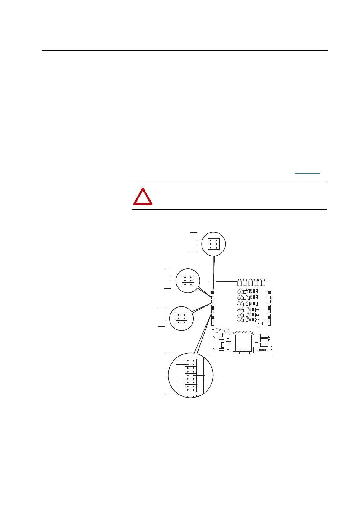
Figure 2.2 Opto-Coupler Checks for Left-Hand Output Power Module
!
ATTENTION: Running the drive with the DC bus wires
disconnected will damage the ASIC Boards. You must reconnect
these wires before running the drive.
H5H7H9H4H6H8
X3
X4
X5
X6
X7
X8
X9
X10
X11
X12
X13
X14
X15
X1
X3
X4
X5
X6
Should measure -15V dc with respect to DC- with no light in WH cable
Should measure +15V dc with respect to DC- with light in WH cable
Should measure -15V dc with respect to DC- with no light in WH cable
Should measure +15V dc with respect to DC- with light in WH cable
Should measure -15V dc with respect to DC- with no light in VH cable
Should measure +15V dc with respect to DC- with light in VH cable
Should measure -15V dc with respect to DC- with no light in VH cable
Should measure +15V dc with respect to DC- with light in VH cable
Should measure -15V dc with respect to DC- with no light in UH cable
Should measure +15V dc with respect to DC- with light in UH cable
Should measure -15V dc with respect to DC- with no light in UH cable
Should measure +15V dc with respect to DC- with light in UH cable
Should measure -15V dc with respect to DC- with no light in WL cable
Should measure +15V dc with respect to DC- with light in WL cable
Should measure -15V dc with respect to DC- with no light in WL cable
Should measure +15V dc with respect to DC- with light in WL cable
Should measure -15V dc with respect to DC- with no light in UL cable
Should measure +15V dc with respect to DC- with light in UL cable
Should measure -15V dc with respect to DC- with no light in UL cable
Should measure +15V dc with respect to DC- with light in UL cable
Should measure -15V dc with respect to DC- with no light in VL cable
Should measure +15V dc with respect to DC- with light in VL cable
Should measure -15V dc with respect to DC- with no light in VL cable
Should measure +15V dc with respect to DC- with light in VL cable

 Loading...


