2-8 Component Test Procedures
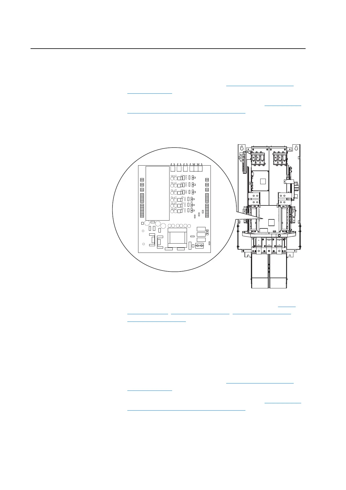
Checking Fiber Optic
Connections to the Gate
Driver Boards
Damaged or improperly connected fiber optic cables can cause apparent
Gate Driver Board malfunctions.
1. Remove power from the drive. Refer to Removing Power from the
Drive on page 3-3.
2. Remove the covers from the power structures. Refer to Removing the
Covers from the Power Structures on page 3-15.
3. On Power Structure #1, locate the Gate Driver Board on the front of the
power structure.
4. Verify the fiber optic cables are properly connected (refer to Figure
B.4 on page B-5, Figure B.5 on page B-6, Figure B.6 on page B-7 or
Figure B.7 on page B-8
).
5. Disconnect the cables and inspect them for scratches and cracks.
6. Reconnect the cables, replacing any damaged cables.
7. Repeat steps 3 - 6 for Power Structure #2.
Conducting Gate Driver
Board Measurements
1. Remove power from the drive. Refer to Removing Power from the
Drive on page 3-3.
2. Remove the covers from the power structures. Refer to Removing the
Covers from the Power Structures on page 3-15.
H5H7H9H4H6H8
X3
X4
X5
X6
X7
X8
X9
X10
X11
X12
X13
X14
X15
X1
Note: There is one Gate Driver Board
for each Power Structure in the drive.

 Loading...


