2-14 Component Test Procedures
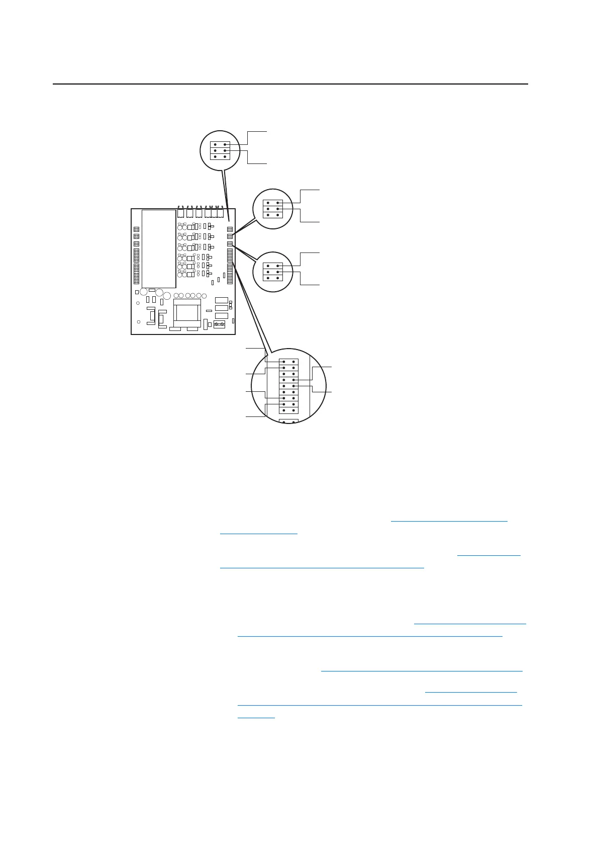
Figure 2.3 Opto-Coupler Checks for Right-Hand Output Power Module
Checking Rectifying Module
(on AC Input Drives Only)
Important: This procedure requires special equipment and training. Only
qualified and trained personnel should perform these
procedures.
1. Remove power from the drive. Refer to Removing Power from the
Drive on page 3-3.
2. Remove the covers from the power structures. Refer to Removing the
Covers from the Power Structures on page 3-15.
3. On Power Structure #1, visually inspect the pre-charging resistors. If
pre-charging resistors are damaged:
A. Replace the Rectifying Module (See Removing the Right-Side
Output Power Modules and Rectifying Modules on page 3-33).
B. Check the capacitors, rectifiers and external connections for
short-circuits. (See Checking the DC Bus Capacitors on page 2-17
)
C. Check the Output Power Modules (See Conducting Forward
and Reverse Biased Diode Tests for Major Power Components on
page 2-4).
H5H7H9H4H6H8
X3
X4
X5
X6
X7
X8
X9
X10
X11
X12
X13
X14
X15
X1
X8
X9
X10
X11
Should measure -15V dc with respect to DC- with no light in WH cable
Should measure +15V dc with respect to DC- with light in WH cable
Should measure -15V dc with respect to DC- with no light in WH cable
Should measure +15V dc with respect to DC- with light in WH cable
Should measure -15V dc with respect to DC- with no light in VH cable
Should measure +15V dc with respect to DC- with light in VH cable
Should measure -15V dc with respect to DC- with no light in VH cable
Should measure +15V dc with respect to DC- with light in VH cable
Should measure -15V dc with respect to DC- with no light in UH cable
Should measure +15V dc with respect to DC- with light in UH cable
Should measure -15V dc with respect to DC- with no light in UH cable
Should measure +15V dc with respect to DC- with light in UH cable
Should measure -15V dc with respect to DC- with no light in WL cable
Should measure +15V dc with respect to DC- with light in WL cable
Should measure -15V dc with respect to DC- with no light in WL cable
Should measure +15V dc with respect to DC- with light in WL cable
Should measure -15V dc with respect to DC- with no light in UL cable
Should measure +15V dc with respect to DC- with light in UL cable
Should measure -15V dc with respect to DC- with no light in UL cable
Should measure +15V dc with respect to DC- with light in UL cable
Should measure -15V dc with respect to DC- with no light in VL cable
Should measure +15V dc with respect to DC- with light in VL cable
Should measure -15V dc with respect to DC- with no light in VL cable
Should measure +15V dc with respect to DC- with light in VL cable

 Loading...


