Access Procedures 3-19
Removing the 700S Voltage
Feedback Circuit Board
Removal
1. Remove power from the drive (Removing Power from the Drive on
page 3-3).
2. Remove the covers from the power structures. Refer to Removing the
Covers from the Power Structures on page 3-15.
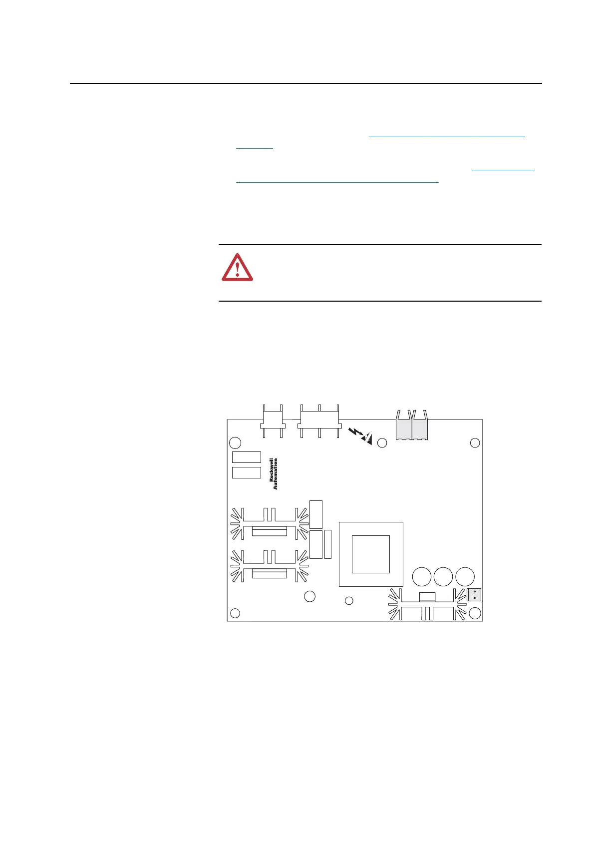
3. Carefully disconnect the fiber-optic cables from J4 and J5 sockets along
the top of the Voltage Feedback Circuit Board, and carefully set them
aside.
Important: Minimum inside bend radius for fiber-optic cable is 25.4 mm (1
in.). Any bends with a shorter inside radius can permanently
damage the fiber-optic cable. Signal attenuation increases with
decreased inside bend radii.
4. Disconnect the cable from J8 socket of the Voltage Feedback Circuit
Board, and set it aside.
5. Remove the five screws which secure the Voltage Feedback Circuit
Board to the drive.
6. Remove the circuit board from the drive.
!
ATTENTION: Hazard of permanent eye damage exists when
using optical transmission equipment. This product emits intense
light and invisible radiation. Do not look into fiber-optic ports or
fiber-optic cable connectors.
J4 J5
J8

 Loading...


