Access Procedures 3-25
Removing the Power
Structures from the Drive
Enclosure
Removal
1. Remove power from the drive (Removing Power from the Drive on
page 3-3).
2. Remove the covers from the power structures. Refer to Removing the
Covers from the Power Structures on page 3-15.
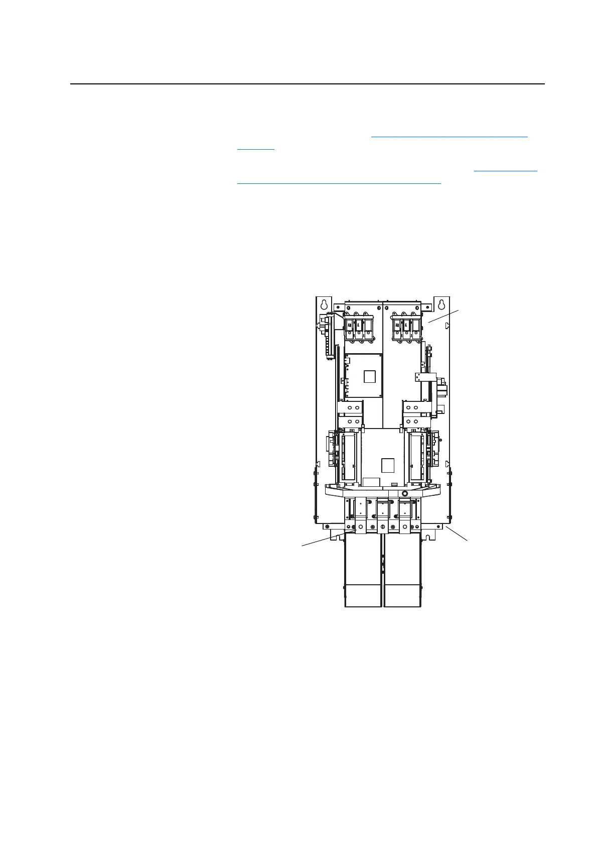
3. On Power Structure 1, remove the motor wiring from the power
structure at the front of the power structure.
4. Remove the ground connection from the lower right rear corner of the
power structure.
5. Remove the input (AC or DC) and brake wiring (if equipped) from the
incoming terminals at the top of the power structure.
6. Follow the instructions in publication PFLEX-IN014, Installation
Instructions - PowerFlex 700S /700H High Power Maintenance Stand,
to install the Maintenance Stand. Remove the power structure by sliding
it onto the rails of the Maintenance Stand.
Note: The Maintenance Stand is designed for removing power
structures from drives supplied in Rittal TS8 enclosures. Alternate
means of removal will be necessary for other types of enclosures.
7. Repeat steps 3 - 6 to remove Power Structure 2 from its enclosure.
Motor Connection
Terminals
AC Power Connection
Te r mi na ls
Ground
Connection

 Loading...


