Component Test Procedures 2-7
If the drive fails any of these measurements, replace both Output Power
Modules for the appropriate Power Structure.
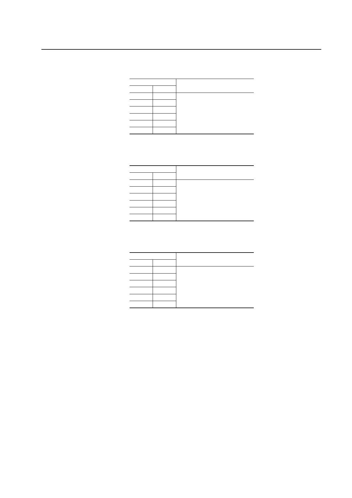
Table 2.F Forward Biased Diode Tests on Output Power Modules for Power Structure
#2
Meter Leads
Nominal meter reading+-
DC- 2U/T1
Meter should display “.0L” (zero load)
DC- 2V/T2
DC- 2W/T3
2U/T1 DC+/R+
(1)
(1)
If the drive does not contain the brake chopper option, the DC+/R+
terminal will be labeled DC+.
2V/T2 DC+/R+
2W/T3 DC+/R+
Table 2.G Reverse Biased Diode Tests on Output Power Modules for Power Structure
#1
Meter Leads
Nominal meter reading+-
1U/T1 DC-
Meter should beep once and value
should gradually rise to about 0.5V
1V/T2 DC-
1W/T3 DC-
DC+/R+
(1)
(1)
If the drive does not contain the brake chopper option, the DC+/R+
terminal will be labeled DC+.
1U/T1
DC+/R+ 1V/T2
DC+/R+ 1W/T3
Table 2.H Reverse Biased Diode Tests on Output Power Modules for Power Structure
#2
Meter Leads
Nominal meter reading+-
2U/T1 DC-
Meter should beep once and value
should gradually rise to about 0.5V
2V/T2 DC-
2W/T3 DC-
DC+/R+
(1)
(1)
If the drive does not contain the brake chopper option, the DC+/R+
terminal will be labeled DC+.
2U/T1
DC+/R+ 2V/T2
DC+/R+ 2W/T3

 Loading...


