2-6 Component Test Procedures
If the drive fails any of these measurements, replace the appropriate
Rectifying Module.
4. Conduct forward and reverse biased diode tests on the Output Power
Modules.
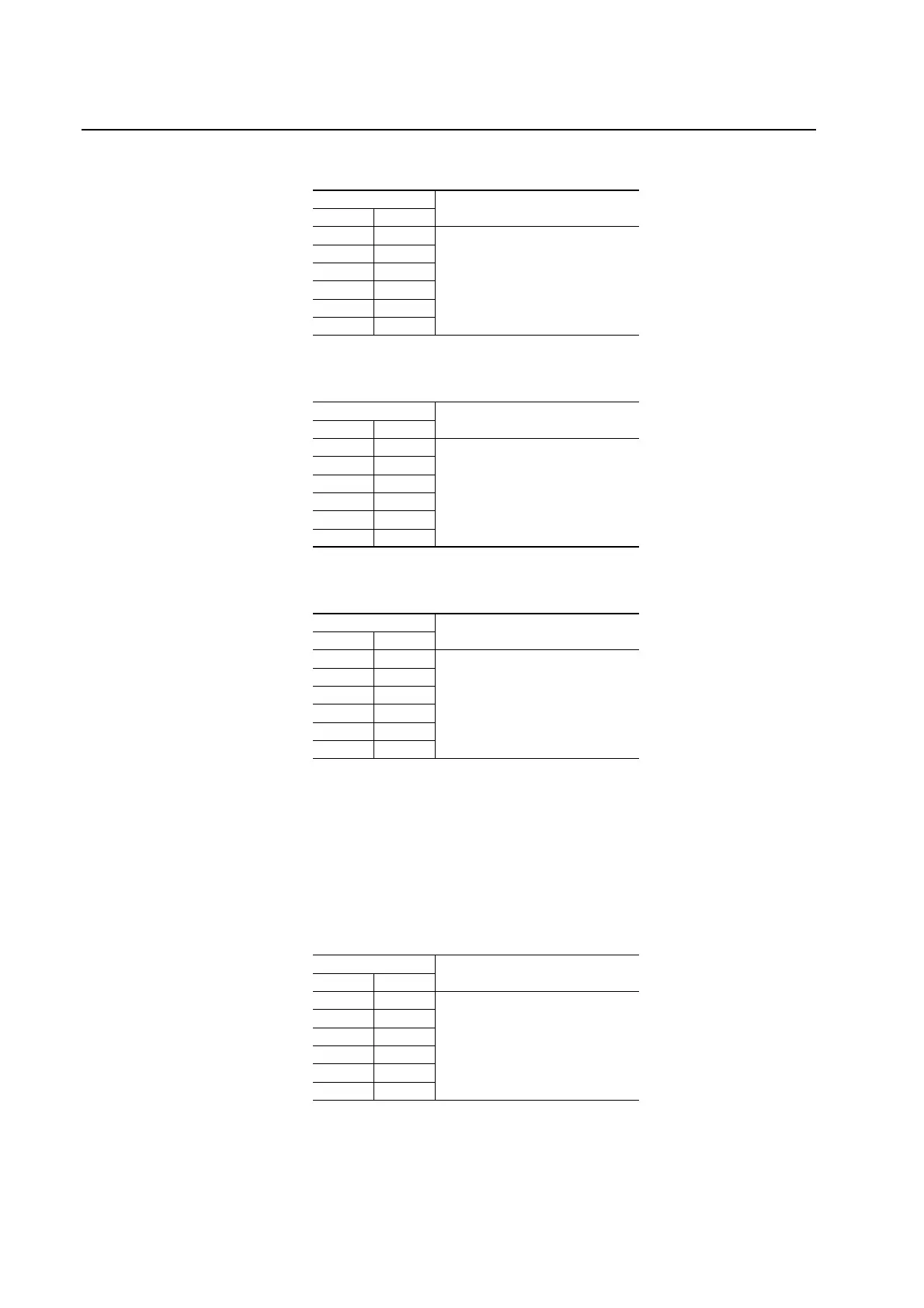
Table 2.B Forward Biased Diode Tests on Rectifying Module for Power Structure #2
Meter Leads
Nominal meter reading-+
DC+/R+
(1)
(1)
If the drive does not contain the brake chopper option, the DC+/R+
terminal will be labeled DC+.
2L1
Meter should beep once and value
should gradually rise to about 0.5V
DC+/R+ 2L2
DC+/R+ 2L3
2L1 DC-
2L2 DC-
2L3 DC-
Table 2.C Reverse Biased Diode Tests on Rectifying Module for Power Structure #1
Meter Leads
Nominal meter reading+-
1L1 DC-
Meter should display “.0L” (zero load)
1L2 DC-
1L3 DC-
DC+/R+
(1)
(1)
If the drive does not contain the brake chopper option, the DC+/R+
terminal will be labeled DC+.
1L1
DC+/R+ 1L2
DC+/R+ 1L3
Table 2.D Reverse Biased Diode Tests on Rectifying Module for Power Structure #2
Meter Leads
Nominal meter reading+-
2L1 DC-
Meter should display “.0L” (zero load)
2L2 DC-
2L3 DC-
DC+/R+
(1)
(1)
If the drive does not contain the brake chopper option, the DC+/R+
terminal will be labeled DC+.
2L1
DC+/R+ 2L2
DC+/R+ 2L3
Table 2.E Forward Biased Diode Tests on Output Power Modules for Power Structure
#1
Meter Leads
Nominal meter reading+-
DC- 1U/T1
Meter should display “.0L” (zero load)
DC- 1V/T2
DC- 1W/T3
1U/T1 DC+/R+
(1)
(1)
If the drive does not contain the brake chopper option, the DC+/R+
terminal will be labeled DC+.
1V/T2 DC+/R+
1W/T3 DC+/R+

 Loading...


