3-8 Access Procedures
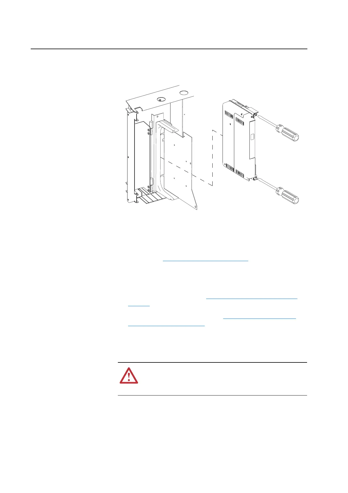
6. Loosen the two mounting screws on the front of the Control Assembly
and slide the control cassette off the mounting bracket.
Installation
Install the 700S Phase II Control Assembly in reverse order of removal,
while referring to Torque Specifications on page 3-1
.
Removing the 700S High
Power Fiber Optic Interface
Circuit Board
Removal
1. Remove power from the drive (Removing Power from the Drive on
page 3-3).
2. Remove the 700S Control Assembly (Removing the 700S Phase II
Control Assembly on page 3-6).
3. Carefully disconnect the fiber-optic cables from the sockets along the
right side of the High Power Fiber Optic Interface Circuit Board (on the
backside of the Control Assembly), and carefully set them aside.
Note: Ribbon cables not shown
for clarity only.
!
ATTENTION: Hazard of permanent eye damage exists when
using optical transmission equipment. This product emits intense
light and invisible radiation. Do not look into fiber-optic ports or
fiber-optic cable connectors.

 Loading...


