Access Procedures 3-31
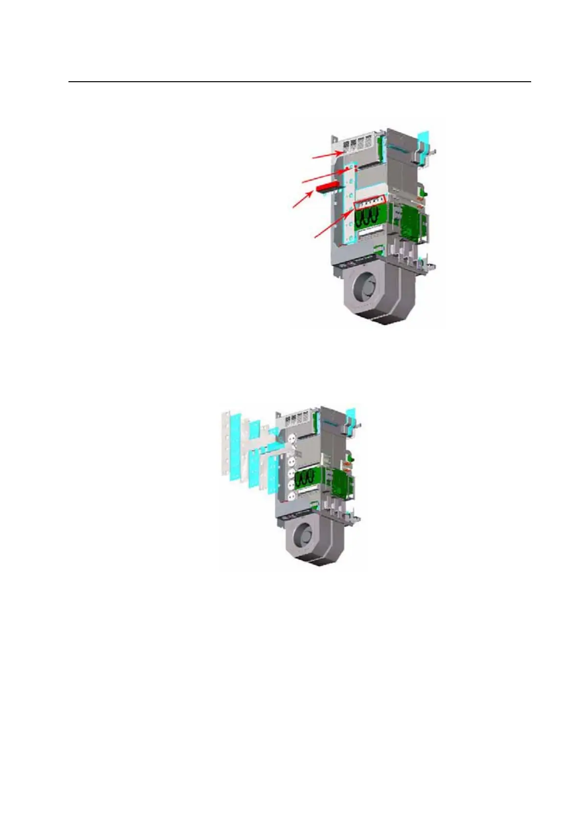
7. Remove the balancing resistor wires from bus bars.
8. Remove the screws that secure the Snubber Capacitors, and remove the
Snubber Capacitors.
9. Remove the screws that secure the DC Bus Bars to the left side of the
power structure, and remove the DC Bus Bars.
10. Remove the screws which secure the Output Power Module to the drive.
11. Disconnect the Power Module Circuit Board from the Adapter Board.
Balancing Resistors
Balancing Resistor Wires
Snubber Capacitors
Snubber Capacitor
Fastening Screws

 Loading...


