Connector Descriptions C-3
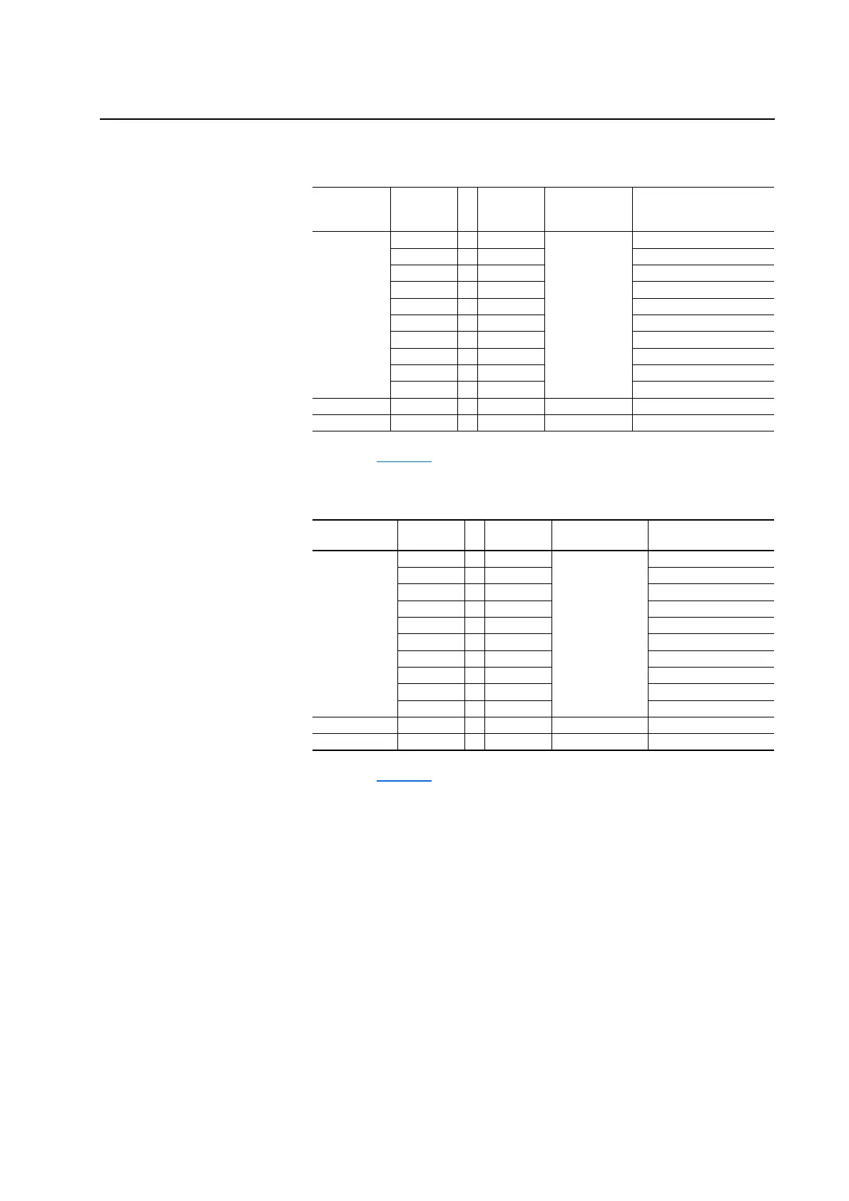
Table C.A ASIC Board on Power Structure #1 to Gate Driver Board on Power
Structure #1 - Phase U Connections
Note: See page C-4 for footnotes.
Table C.B ASIC Board on Power Structure #1 to Gate Driver Board on Power
Structure #1 - Phase V Connections
Note: See page C-4 for footnotes.
ASIC Board
Connector Pin Number to Pin Number
Gate Driver
Board
Connector Description
X3 1 . . . 1 X13 U_Feedback
2 . . . 2 U_Power_OK
3 . . . 3 U_DTR
(1) See Note Below
4. . .4 U_ETR
(2)
5 . . . 5 U_ITR
(3)
6 . . . 6 U_DC-
7. . .7 UI
8 . . . 8 U_DC-_I
9. . .9 U_TEMP
10 . . . 10 U_DC-T
H8 (fiber optic) H8 . . . H4 H4 (fiber optic) UH or Gate Top
H9 (fiber optic) H9 . . . H5 H5 (fiber optic) UL or Gate Bottom
ASIC Board
Connector Pin Number to Pin Number
Gate Driver Board
Connector Description
X4 1 . . . 1 X14 V_Feedback
2 . . . 2 V_Power_OK
3 . . . 3 V_DTR
(1)
4 . . . 4 V_ETR
(2)
5 . . . 5 V_ITR
(3)
6 . . . 6 V_DC-
7 . . . 7 VI
8 . . . 8 V_DC-_I
9 . . . 9 V_TEMP
10 . . . 10 V_DC-T
H10 (fiber optic) H10 . . . H6 H6 (fiber optic) VH or Gate Top
H11 (fiber optic) H11 . . . H7 H7 (fiber optic) VL or Gate Bottom

 Loading...


